
ASCII Video Terminal
![]()
![]()
![]() This is a complete ASCII VT100 compatible video terminal in a single chip. You can use it as a normal serial terminal with keyboard and display or as a single chip controller to add a video output to a Micromite or PICAXE project.
This is a complete ASCII VT100 compatible video terminal in a single chip. You can use it as a normal serial terminal with keyboard and display or as a single chip controller to add a video output to a Micromite or PICAXE project.
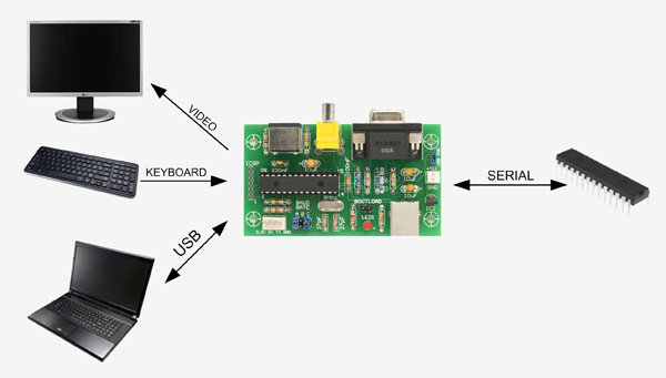
It has a serial interface with TTL or RS232 signal levels, input from a standard PS2 style keyboard and output to a VGA or composite monitor. There is also a USB interface which supports serial over USB and acts as a USB-to-serial converter.
The firmware emulates most features of the DEC VT100 and VT52 terminals and has extensions for graphics (lines, boxes and circles) as well as alternative fonts (large and jumbo).
The entire terminal (video generator, serial interface, etc) is contained in a single low cost chip. You can use it to build a complete terminal (as illustrated on the left) or as a single chip video driver, keyboard interface or whatever.
The ASCII Video Terminal project was described in the July 2014 issue of Silicon Chip magazine.
This web page provides all that you need to build the project but for a fuller description you should refer to the original magazine article. Back issues of the article can be purchased from Silicon Chip or electronic access can be purchased for about the cost of the printed issue.
Specifications
- Single chip ASCII video display terminal with VT100 and VT52 emulation
- VGA or Composite Video output with automatic switch over. Composite can be PAL or NTSC.
- VGA can display 24 lines x 80 characters or an extended resolution of 36 lines x 80 characters
- Composite video can display 18 lines x 48 characters (PAL) or 15 lines x 44 characters (NTSC)
- Standard PS2 compatible keyboard input with support for standard US keyboard layout or French, German, Italian, Belgian, Russian or United Kingdom keyboard layouts
- TTL or RS232 serial input/output. Baud rates from 40 to 1,000,000 bits per second with odd, even or no parity and one or two stop bits
- USB input with serial emulation. This can be used as a USB to serial converter
- Extended VT100 terminal emulation. Extensions include graphics codes for drawing lines, boxes and circles (which can be hollow or filled)
- Graphics resolution is 480x288 pixels in VGA 25 line mode, 480x432 pixels in VGA 36 line mode, 288x216 in PAL composite and 264x180 pixels in NTSC composite mode
- Three built in fonts (standard, large and jumbo) and four character attributes (normal, underline, reverse and invisible)
- Power requirement is 5V at 50mA plus any current drawn from the 3.3V pin on the serial connector
Circuit
The ASCII Video Terminal is based on a low cost 32-bit microcontroller from Microchip. Under control of its firmware this chip does almost everything including generating the video, decoding the keyboard, driving the USB, sending/receiving data over the serial interface and running the VT100 emulation. The only other significant component is a three terminal regulator used to provide the 3.3V power to the microcontroller.
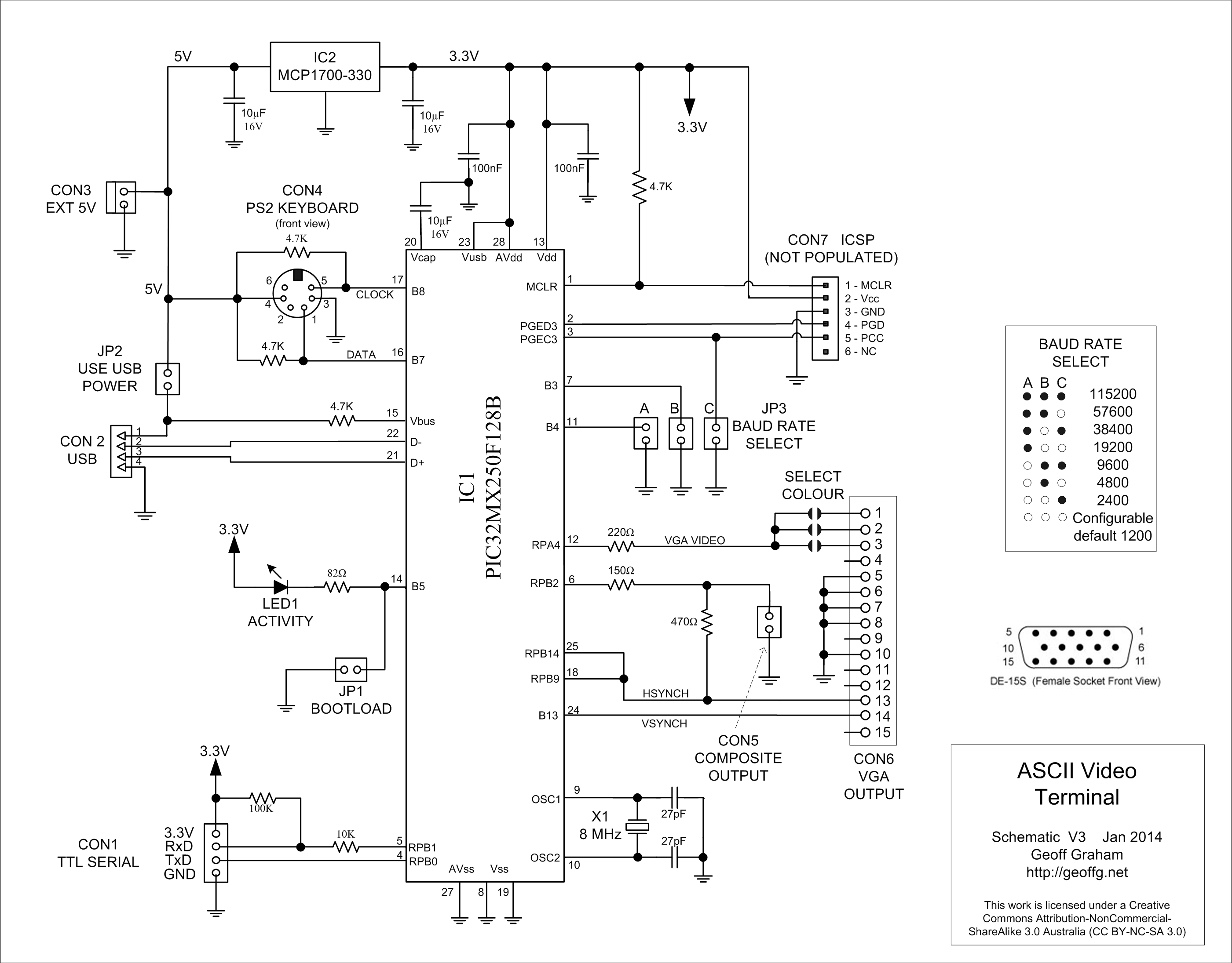
Click on the image to download a high resolution copy
The video is generated from separate I/O pins on the microcontroller for the VGA and composite outputs. This enables the signal levels to be optimised to suit the type of display. Note that only one type of monitor should be connected at any one time.
The microcontroller automatically determines the type of terminal that is connected on power up. It does this by measuring the resistance from pin 12 to ground. If it is less than 2K it assumes that a VGA monitor is plugged into the VGA connector and the video should be generated at pin 12 with the correct timing for a VGA monitor. Otherwise the firmware assumes that a composite monitor is connected and the video is then generated from pin 6 with timing to suit the PAL standard (NTSC can be selected on the setup screen).
The remainder of the circuit is reasonably standard and does not need explanation.
Construction
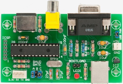
The complete circuit is housed on a single PCB. If you wish to mount the board in a box the dimensions and mounting holes are sized to suit a standard small ABS box 60x120x30 mm (Altronics H0216 or Jaycar HB6032).
A construction pack can be downloaded from the bottom of this page. This contains the circuit, parts list, PCB design files and the firmware. The only specialised components required are the microcontroller and the PCB board.
You can buy the chip pre programmed from Silicon Chip magazine or, if you have a PIC32 programmer (ie, the Microchip PICKit3), you can buy a blank microcontroller and program it yourself. See this page for details.
If you need to program your own chip you should solder a six pin header in the PCB at the location labeled ICSP (In Circuit Serial Programmer) so that you can connect the programmer. When you program the chip make sure that you do not have any jumpers on the baud rate pins as that will interfer with the programmer's signals.
For the printed circuit board you can send the Gerber files (in the construction pack) to a fabrication house who will make it for you. I use iMall and for $20 they will make ten of these boards - you probably will not need ten boards but what the heck. Alternatively you can also buy the board from Silicon Chip.
The PCB is easy to assemble, refer to the high resolution photograph in the construction pack for the component placement. Note that the PCB is designed to take the two common types of RCA connectors (for composite output) so there are multiple holes for this component.
One thing you do need to do is select the colour of the text on the VGA monitor. Just below the VGA connector there are three solder jumper pads each labeled with a different colour. Place a blob of solder on one of these to select your colour (I recommend green).
Usage
The following lists the jumpers and connectors on the board.
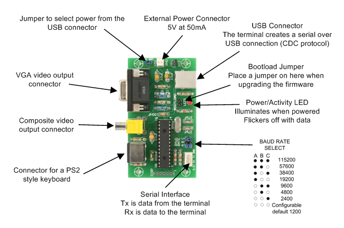
When a key is pressed on the keyboard the ASCII character is sent out on the serial interface Tx line. Also, when anything is received from the USB interface it is also sent out on the same serial Tx line.
When a character is received from the serial interface (on the Rx line) it is displayed on the video output and also sent out on the USB interface (if it is connected to a computer).
Normally the device connected to the serial interface will echo any characters received back to the terminal so you can see the character on the screen. But, if you do not have anything connected on the serial interface, nothing will be echoed. So, if you are testing the terminal make sure that you place a jumper across the Tx and Rx pins. That way anything you type will be echoed back and you can the result of your typing on the screen.
The ASCII Video Terminal emulates most codes recognised by the original VT100 - at the bottom of of this page you can download the definitive list of the escape codes that this terminal will accept. For a more complete description of each code you should also download a copy of the VT100 User Guide (also available below).
Set-Up Menu
The terminal can be configured with a number of options on the SetUp menu. This menu is invoked by using SHIFT- F12 on the keyboard and the menu will be displayed on the video display. Note that this means that you cannot set any options over the USB interface, you must connect a keyboard and monitor.
In the Set-Up menu you can select the number of lines to display in VGA mode (24 or 36), the type of composite output (PAL or NTSC) and the type of keyboard connected (French, German, US, etc). For the serial interface you can select the number of bits, parity and the number of stop bits. 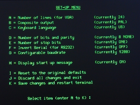
If you are connecting to a RS232 circuit you can invert the serial data stream. No other changes are required as the 10K resistor on pin 5 of the microcontroller will protect the micro from the ±12V signals used by RS232. The output from the microcontroller is only 0 to 3.3V but most RS232 systems will accept this as a valid signal.
The configurable baudrate option lets you select the baudrate when there are no jumpers placed on the baudrate jumper block. The baud rate can be any number from 40 to 1,000,000 bits per second.
Finally, you can suppress the startup message (version number and copyright) with option H.
All these options are permanently saved and recalled at start up.
Single Chip Controller
You do not need to build the complete terminal if you only want just one or two functions - in that case you can use the microcontroller as a specialised single chip controller. For example, the following circuit can be used if you just want to add a composite video display to your project. 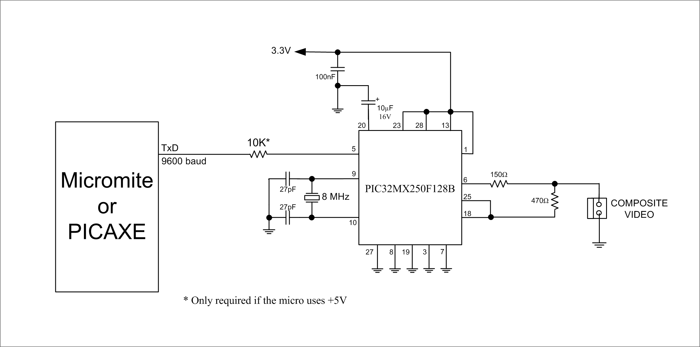
There are many low cost composite monitors on sale on eBay that are intended for car reversing cameras but work perfectly with this circuit. I bought a 4.3 inch monitor for $19 on eBay which, coupled with the low cost chip used in this project, enables you to add a sophisticated front panel display for a Micromite or PICAXE based project for less than $30.
You can do a similar thing if you just want to use the terminal as a USB to serial bridge. Just leave off the other components and use only the USB and serial interfaces.
Firmware Update
A new version (Ver 1.3) of the firmware is available from the download area below. The only new feature (compared to V1.2) is the ability to turn the cursor off and on (see the change log included in the zip file for details). You do not need to upgrade if you do not need this feature.
However, if you are running V1.0 or V1.1 you should upgrade as this version (and V1.2) fixes two bugs related to composite video. These bugs also caused corruption of the USB communications when the terminal was running in composite PAL mode. Because the terminal defaults to composite PAL when no monitor is connected this will interfer with the use of the ASCII Video Terminal as a serial-USB bridge.
For these reasons it is recommended that the upgrade be applied if you are running V1.0 or V1.1.
Full software and instructions to perform the upgrade are included in the upgrade file. You only need a Windows computer and the upgrade takes less than a minute.
Other Versions
Gary Kaufman has created an updated PCB for the ASCII Video Terminal which, amongst other improvements, includes an RS232 driver and a USB Type-A connector for a USB keyboard (PS2 keyboards can be hard to find these days). He has posted his work on Hackaday. Go to https://hackaday.io/project/173216-ascii-video-terminal
David Hansel has modified the firmware to support a USB keyboard and that will work with Gary Kaufman's updated PCB. You can find this at GitHub: https://github.com/dhansel/TerminalUSB
Peter Hizalev on Tindie offers a modified design and firmware. His firmware uses a different clock frequency (and crystal) which produces a clearer image (I have not tested it). You can purchase the PCB, the pre programmed microcontroller or a full kit of parts (including the programmed microcontroller) from him by following this link.
| Firmware Upgrade to V1.3 | DOWNLOAD |
| ASCII Video Terminal Construction Pack (includes schematic, parts list, firmware, etc) | DOWNLOAD |
| Escape codes recognised and generated by the ASCII Video Terminal | DOWNLOAD |
| The original VT100 Users Guide (for a more complete explanation of each escape code) | DOWNLOAD |
| ASCII Video Terminal Source Code (requires Microchip MPLAB X and XC32 compiler) | DOWNLOAD |
| Windows Serial Port Driver (for connection to the Terminal via USB - Windows only) | DOWNLOAD |