
Programming PIC Microcontrollers
![]()
![]()
 Most of my projects rely on a Microchip PIC microcontroller which must be programmed with the appropriate firmware to do its job. But programming these small processors can be a big hurdle for a lot of people.
As it happens, Microchip try to make it easy for you by providing cheap programmers and free software. They hope that this will encourage you to buy more of their chips. The result is a win-win situation.
So, in this article I intend to show how easy it is to program a PIC microcontroller with an investment of less than $20.
Note that this page only covers programming the Microchip PIC series of processors. There are many other microcontrollers out there (Atmel, TI, etc) and these will require different programmers and software.
The Microcontroller
Nearly all modern microcontrollers use flash memory for storing the program. This is why programming a microcontroller is frequently referred to as "flashing" the chip.
Flash memory can be erased and reprogrammed many times and the stored data is retained even when the power is removed. In addition to the program there are other memories in the chip that are also programmed in the one operation; these include configuration settings (sometimes called "fuses"), EEPROM (another type of erasable memory) and bootload areas. The information to program all of these is contained in the one file which generally has an extension of .hex (for example "FirmwareV1.hex"). Often the file is referred to as a "hex file".
Programmers
There are a number of programmers that you can purchase to do the job. The following is a brief rundown with the comments orientated towards a hobbyist who only needs to program the occasional chip.
ICD3 and ICD4. These are high end (and expensive) programmer/debuggers from Microchip. They are intended for use by developers and are overkill for the average hobbyist.
PICkit3 and PICkit4. These are the best choice for a hobbyist as they are low cost and support all the chips made by Microchip. The PICkit4 is the latest and fastest but the PICkit3 still does a good job. The advantage of the PICkit3 is that many Chinese manufacturers are making cheap clones which can be found on eBay.
PICkit2. This is an old design and does not support the more recent chips such as the PIC32 series. There are many PICkit2s on eBay at very cheap prices but you should avoid them as they are next to useless.
The MPLAB® Snap In-Circuit Debugger/Programmer is the latest from Microchip and quite cheap (US$15 + freight). It does a great job and can be purchased from Microchip themselves, distributors such as Mouser and on eBay. It is a good choice if you wish to stay away from the Chinese clones of the PICkit3
If you just want to program the PIC32 chips used for the Maximite and Micromite an even cheaper alternative is the Microbridge. This is based on a single chip costing less than US$2 and it has its own web page here. The main problem with the Microbridge is that you need to get the programming firmware into the chip in the first place so you end up with a chicken and egg situation requiring you to purchase a programmer such as the PICkit3 anyway.
PICkit 3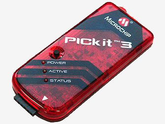
Because the clones of the PICkit 3 are so cheap and are supported by Microchip's software and will program almost any Microchip microcontroller the following will concentrate on the PICkit 3 as the programmer of choice.
You can buy the genuine PICkit 4 from Microchip for US$80 + freight (link) or from their distributors. The original PICKit 3 is still available (part number PG164130) with some distributors but they are slowly dissapearing.
However I recommend the clones of the PICkit 3 which seem to work just as well but are much cheaper. As a test I purchased one for US$25.00 with free freight and I cannot fault it. The Microchip software recognised it as a genuine PICkit 3 and it worked just as well as the genuine article.
A good place to find cheap clones is eBay. Just search for PICkit3. However, be carefull - many suppliers also offer the PICKit 2 at a very cheap price but don't be fooled, you need the PICKit 3 version.
So, if you just want a cheap method of programming Microchip microcontrollers purchasing a Pickit 3 clone would be the way to go. At their ridiculously low prices you can afford to buy one just to program a single chip and then add it to your tool box for a possible future project.
PICkit 2
Above I recommended against purchasing the PICkit 2 but if you do have one of these you can use the programming software developed by Jaakko Kairus called PICkit2minus. This supports a wide range of 8, 16 and 32-bit Microchip microcontrollers including the PIC32 used in the Micromite series. It has a great graphical user interface and will work with the PICkit 3 so it can also be used as your main programming software for both the PICkit 2 and 3.
PICkit2minus can be downloaded from here.
In Circuit Serial Programming
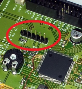 Most Microchip microcontrollers use an In Circuit Serial Programming connection (abbreviated to "ICSP") to transfer the program to the chip. Normally the printed circuit board (PCB) will have a connector for this and it will look something like the connector highlighted in the photo on the right.
If you do not have such a connector (perhaps you are programming a bare chip) you will have to figure out the connections yourself. The following table, which lists the pinouts on the ICSP connector, should help:
| PIN | NAME | USAGE |
| 1 | MCLR | Master reset pin on the microcontroller |
| 2 | Vdd | Microcontroller supply voltage |
| 3 | Vss | Supply ground or zero volts pin |
| 4 | PGD | Programming data signal |
| 5 | PGC | Programming clock signal |
| 6 | - Not Used - |
The programmer monitors the voltage on pin 2 (Vdd) and uses that to determine if the chip to be programmed is actually powered up. To start the programming operation the programmer will drive pin 1 (MCLR) to a voltage higher than Vdd (normally 12 to 15 volts). It then transfers the data using pin 4 (PGD) and pin 5 (PGC). Internal logic in the chip will take that data and write it to the chip's flash memory.
Connecting It Up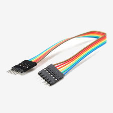
In the above illustration of a PCB you would be able to plug the PICkit 3 directly onto the six pin ISCP header connector. Pin 1 of the PICKit 3 connector is marked with a white triangle and normally pin 1 of the connector on the PCB is marked with the number 1 or some other symbol.
If you cannot fit the programmer into the space you will need a six conductor cable with a male header and a female header at the other end as illustrated on the right (my clone came with this which was handy).
When programming a microcontroller you only need to supply power to the chip (and connect a capacitor to Vcap if the chip has that pin). You do not need any other components as the chip will startup using its internal oscillator and that is all that the programmer will need.
The Software
To drive the PICkit 3 you need to install Microchip's MPLAB X software development system on your personal computer. This comes in various versions for Windows, Mac OS and Linux. Unfortunately the full install includes lots of stuff that you do not need (such as a full integrated development environment) but the important part is MPLAB IPE which is the programmer component (IPE stands for Integrated Programming Environment). This is normally installed as an icon on your desktop.
A simpler alternative is PICKITminus which can be downloaded from here.
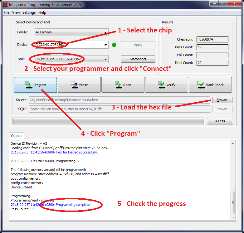
When you startup MPLAB IPE you have a fairly straightforward screen which allows you to specify the part number of the chip and the hex file to program into it. Just go through the numbered steps illustrated below to program your chip.
Errors
When you click on the "Program" button the software will instruct the PICkit 3 to erase the chip, program it with the new firmware then read back that program to verify that it has been properly written. At the end you should get the message "Programming complete".
Of course it may not be as easy as that. Three of the more common errors that you might encounter are:
"Target Vdd not detected". This usually means that you have not correctly connected to the ISCP programming connector or that the device that you are trying to program is not powered.
"Failed to program device" or "Cannot read device ID". The programmer could tell that you had connected to something (because Vdd was present) but it could not communicate with the chip. This usually means that something was interfering with the MCLR, PGD and/or PGC lines (ie, they were not connected or other components were loading down the signals).
"Target Device ID does not match expected Device ID". This means that the programmer has detected a device that is different from the device that you specified in step 1 above.
Power To The Device
Normally the chip that you are programming will be powered by the circuit that surrounds it but you also have the option of powering the chip from the PICKit 3 itself. This can come in handy when you are programming a chip which will be later plugged into its eventual home but as the moment is just a free chip. Note that the PICkit 3 can supply a maximum of 30mA so it is only good for powering a bare chip and nothing else.
To tell the PICkit 3 to provide the power you need to select Settings --> Advanced Mode. You are then required to put in a password ("Microchip") to enter Advanced Mode. Finally select the Power tab and tick "Power Target Circuit from Tool". The PICkit 3 will then supply power out of pin 2 (Vdd) rather than just measuring the voltage on that pin (which is what it normally does).