The Game of Pong
![]()
![]()
![]() When I was getting into microcontrollers I needed a project that would be a suitable learning vehicle. It had to be simple electronically but complex in software, thus I decided to build the game of Pong.
When I was getting into microcontrollers I needed a project that would be a suitable learning vehicle. It had to be simple electronically but complex in software, thus I decided to build the game of Pong.
Later, when I researched the game on the Internet, I discovered that many people have had exactly the same idea—there were many games of Pong out there. Not to worry though, it was a great learning experience and I can now add my version to the world’s collection of Pong games.
This game is designed for ordinary TVs and outputs audio and a standard monochrome PAL composite video signal complete with sync pulses. It only uses one IC and a few passive components so it is quite simple to build.
Pong
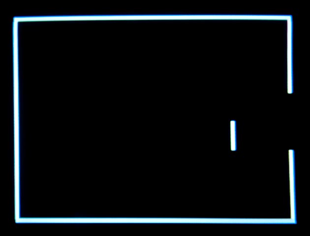
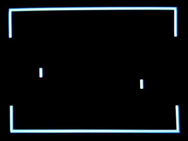
For those who do not know, Pong is a two dimensional game of tennis played on a TV screen. Two players each have a bat which can be moved and a goal that must be defended. The ball is an electronic blob of light that bounces off walls and bats until it hits someone’s goal.
 It is a simple game and was one of the first electronic games invented. It was popularised by Atari who released the first console game in 1972 and then went on to release a home version a few years later. Overall it was a great success and formed the foundation of Atari’s early profitability.
I built a version of Pong in 1975 based on TTL logic and it ended up using six printed circuit boards and a large power supply. So you can see why I was enamoured of the idea of building the entire game inside a single 14 pin chip.
In this implementation each player has a bat that can be moved up and down to intercept the ball.
When the ball hits a bat it bounces off with a low beep sound and when it hits a wall it will ricochet off with a higher pitched beep sound. As the ball bounces around the screen each player must move their bat up and down to intercept the ball and bounce it back to protect their goal. When the ball hits a goal a long low beep is sounded and the ball vanishes. Pressing the start button will start a new game.
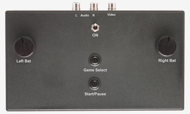
There are two push buttons on the front panel. One will start a game or, if pressed while the game is running, will pause the game. The other button will select the type of game and difficulty. You can select between single player where you bounce the ball off a blank wall in front of you while defending your goal behind you, or a two player game where you are both defending your goals. For each of these game types there are four levels of difficulty. Each press of the “Game” button will step you through each level of difficulty in each type of game. After eight presses you will have cycled through all options.
There is an off/on switch and if the game has been left on but not been used for a while it will automatically put itself into a sleep mode to conserve the battery. You can reset it by turning it off and then on again.
 |
Left
Right
|
 |
|---|
The Circuit
The circuit is simple. At its core is a PIC 16F688 microcontroller with its clock derived from a 16MHz crystal. The choice of 16MHz was deliberate—after being divided by 4 in the PIC’s clock circuitry and then divided by 256 in Timer 0 it gives us the exact horizontal scanning rate used in PAL TV’s (15.625KHz).
Two 10KΩ linear potentiometers are used for the left and right bat control, the microcontroller reads the voltage on the wiper to determine the position of the bat. Note that the top of the potentiometers is connected to an output pin of the microcontroller. Normally this pin is held high so that there is a voltage across the potentiometers but when the microcontroller goes to sleep this output is set low so that there is no current flowing through the potentiometers to drain the batteries.
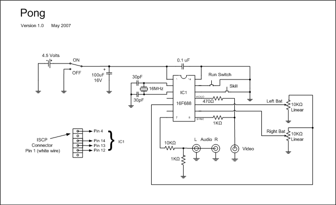 The video is created by summing the current through the 1KΩ and 470Ω resistors. The 1KΩ resistor provides the sync pulses and the corresponding output of the microcontroller (pin 8) is normally high and goes low during a sync pulse. The video signal is provided by pin 11 via the 470Ω resistor. This pin is normally low and goes high to draw on the screen. The combination of highs and lows on the sync and video outputs is summed by the two resistors and, in conjunction with the 50Ω load presented by the TV on the video output, results in the correct voltage levels for a TV video signal.
Note that all this assumes that the TV presents a 50Ω resistive load across the video output. If you test the circuit without plugging the video into a TV you will need to provide an external 50Ω load.
The sound output is a square wave generated on pin 7 of the microcontroller. The 10KΩ and 1KΩ resistors drop the voltage to a level compatible with audio line inputs. The pushbutton switches are connected to inputs of the microcontroller that are pulled high by internal resistors so when the button is pressed the chip will see a low voltage.
When the microcontroller goes into sleep mode it draws very little current. This could be a problem if the user quickly switched the unit off and then on again to “wake up” the device after it has gone to sleep. This is because the 100uF capacitor would take a few minutes to discharge. So this is why the power switch shorts the supply line to ground when turned off. It discharges the 100uF capacitor so the microcontroller sees a rising supply voltage when the switch is returned to the on position and starts up in normal (not sleep) mode.
Finally, the ISCP connector is for re-programming the microcontroller in circuit. Most people would not want to do that, so you can leave it out.
The Firmware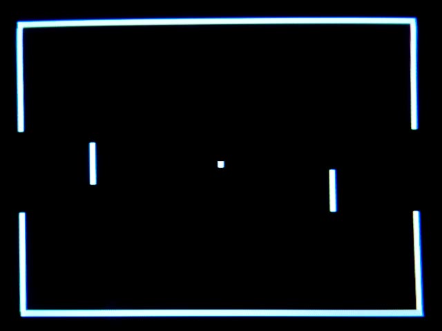
The firmware is written in C using the CCS C Compiler and is available from the download section at the end of this page. Unfortunately, if you want to change the code, you will have to pay for this compiler as there are no free or open source compilers available for the low end PIC series.
Compared to the hardware, the firmware is much more complex and this is where the real work is done. Even then, most of the hard work is done in the Timer 0 interrupt. Timer 0 generates an interrupt every 64uS which corresponds to the horizontal sync rate. Because there is much to be done as the CRT beam sweeps across the TV’s phosphor the interrupt code is written in optimised assembler.
Timer 0 Interrupt
Within the interrupt the first thing that the code does is generate the horizontal sync pulse, following that it figures out what part of the screen it is drawing depending on the vertical position of the beam. There are five regions - for example, the blank area at the top of the screen, the top boundary, the middle of the screen, etc. Within each region the interrupt code figures out what needs to be drawn on the screen for this particular scan line and writes the data to an array which represents pixels across the screen in that scan line.
As the beam scans across the screen the firmware runs through this array pumping the data out as video to the TV. While the beam is moving the assembler is optimised to simply read the pixel data, shove it onto the output pin, read the next pixel, shove that one out, and so on across the screen. Finally, at the end of the scan line the code returns from interrupt. In fact the microcontroller spends most of its time in the interrupt, the mainline code can only run at the end of a scan line, and during vertical sync pulses.
Because of the optimised assembler code and the method the firmware uses to stream the video data, the microcontroller can draw reasonably fine lines on the TV screen. Other people have addressed the problem in other ways, some have used faster processors and some have skipped drawing things like the boundaries.
Mainline Code
The main code running on the microcontroller is oblivious to all the activity within the timer 0 interrupt. It is responsible for checking if a button has been pressed, reading the position of the bats, checking for a collision between the ball and something else and moving the ball around the screen. The result of this is a number of variables that are updated (eg, the ball’s X and Y positions). These variables are read by the timer 0 interrupt code to determine where to draw objects (eg, the ball). All the mainline code needs to do is update these variables, the interrupt code magically does the rest.
 The current code only uses about one third of the microcontroller’s memory so there is plenty of opportunity to add extra features. First on the list would be scoring, secondly perhaps would be to use proper analogue joysticks and allow the player’s bats to move in two dimensions. But for me it served its purpose… as a learning vehicle.
Construction
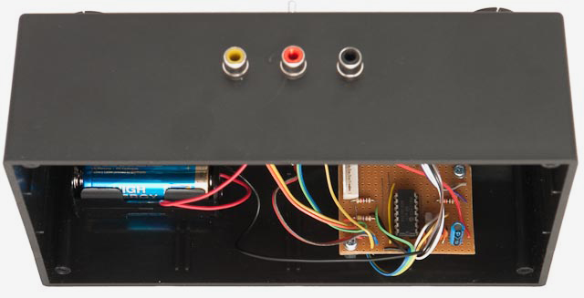
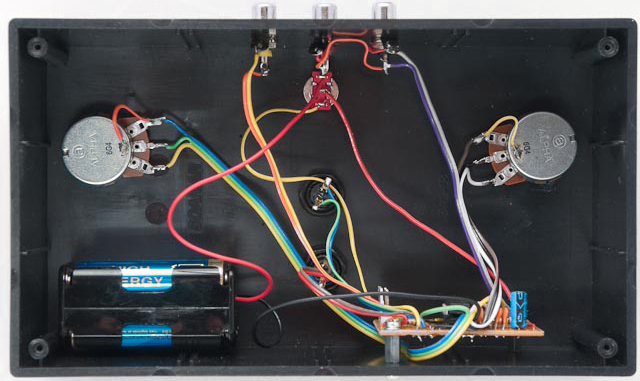
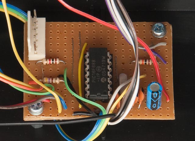
Because the circuit was so simple I built it on a piece of perforated strip board. The rest was done using point to point wiring. It was mounted in a utility box that was large enough for two people to grab hold of their controls.
A future improvement would be to make hand held controllers connected to the main unit by cables.
| Schematic v1.0 | DOWNLOAD |
| Firmware - HEX programming file v1.0 | DOWNLOAD |
| Firmware - Source v1.0 | DOWNLOAD |
