The Standard Micromite
![]()
![]()
 The Standard Micromite comes in both 28 and 44 pin packages. It runs at 48MHz and has 60KB memory for BASIC programs (enough for programs up to 2500 lines long).
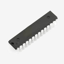
The 28-pin package is a dual inline package (DIP) which can be plugged into an IC socket and easily soldered onto prototyping boards.
The 44-pin package is surface mount but the pins have a wide 0.65mm pitch which makes it relatively easy to solder. In addition there are a number of carrier PCBs available which route the pins to a breadboard friendly row of 0.1" pins.
If you are getting into microcontrollers the standard Micromite is the best avenue. The cost of the chip is modest (about US$4) and it provides an easy programming environment that is quite powerful at the same time.
The first Micromite was introduced in the May 2014 issue of Silicon Chip magazine and then updated in the January 2015 issue.
Back issues of the articles can be purchased from Silicon Chip or electronic access can be purchased for about the cost of the printed issue.
Other pages related to the Micromite include:
- Overall introduction to the Micromite
- Firmware downloads
- The Micromite Plus
- The Micromite LCD Backpack
- Programming the PIC32
Standard Micromite Features
- A fast 32 bit CPU with 256K of flash and 64K RAM running a powerful BASIC interpreter. 60KB of non volatile flash memory is reserved for the program. 52KB of RAM is available for BASIC variables, arrays, buffers, etc. This is sufficient for quite large BASIC programs up to 2500 lines or more and typically it will execute a program at 30,000 lines per second.
- The Microsoft compatible BASIC interpreter is full featured with floating point, 64-bit integers and string variables, long variable names, arrays of numbers or strings with multiple dimensions, extensive string handling and user defined subroutines and functions.
- Compiled C or assembler routines can be inserted into the BASIC program for speed or to access special features of the PIC32 microcontroller.
- Nineteen input/output pins are available on the 28-pin chip and 33 I/O pins on the 44-pin chip. These can be independently configured as digital input or output, analog input, frequency or period measurement and counting. Ten or more of the pins can be used to measure voltages and another seven or more can be used to interface with 5V systems.
- Programming and control is done via a serial console (TTL voltage levels) at 38400 baud (configurable). Once the program has been written and debugged the Micromite can be instructed to automatically run the program on power up with no user intervention. Special software is not needed to develop programs.
- A full screen editor is built into the Micromite. This only requires a VT100 terminal emulator and can edit a full program in one session. It includes advanced features such as search and copy, cut and paste to and from a clipboard.
- Easy transfer of programs from another computer (Windows, Mac or Linux) using the XModem protocol or by streaming the program over the serial console input.
- TFT LCD display panels using the ILI9341 and other controllers are supported allowing the BASIC program to display text and draw lines, circles, boxes, etc in full colour. Resistive touch controllers on these panels are also supported allowing them to be used as sophisticated input devices. These LCD panels typically cost US$7 and provide a low cost, high tech graphical user interface to your program.
- Input/Output functions in MMBasic will generate pulses (both positive and negative going) that will run in the background while the program is running. Other functions include timing (with 1 mS resolution), BASIC interrupts generated on any change on an input pin and an internal real time clock.
- A comprehensive range of communications protocols are implemented including I2C, asynchronous serial, RS232, IEEE 485, SPI and 1-Wire. These can be used to communicate with many sensors (temperature, humidity, acceleration, etc) as well as for sending data to test equipment.
- Built in commands to directly interface special devices such as infrared remote controls, the DS18B20 temperature sensor, LCD display modules, battery backed clock, distance sensors, numeric keypads and more.
- Up to five PWM or SERVO outputs can be used to create various sounds, control servos or generate program controlled voltages for driving equipment that uses an analogue input (eg, motor controllers).
- Special embedded controller features in MMBasic allow the clock speed to be varied to balance power consumption and speed. The CPU can also be put to sleep with a standby current of just 90µA. While in sleep the program state and all variables are preserved. A watchdog feature will monitor the running program and can be used to restart the processor if the program fails with an error or is stuck in a loop.
- The running program can be protected by a PIN number which will prevent an intruder from listing or modifying the program or changing any features of MMBasic.
- Power requirements are 2.3 to 3.6 volts at 6 to 31mA.
Remember, all of the above features are internal to the Micromite. The only extra component required is a 47µF capacitor.
Getting Started
There are two versions of the standard Micromite:
- A 28-pin version based on the Microchip
PIC32MX170F256B
microcontroller is an easy to use 28-pin dual inline package (DIP) that can be plugged into a breadboard or an IC socket.
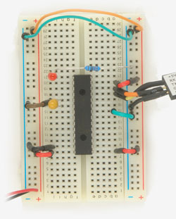
It has 19 I/O pins for interacting with the external world and is shown on the right, plugged into a breadboard. - A 44-pin version based on the Microchip PIC32MX170F256D microcontroller. It has all the features of the 28-pin version plus 33 I/O pins which are under the control of your BASIC program. This is a surface mount chip but there are many ways to use this including soldering it onto a header board or by using the Micromite Module. See, "Development Boards and Components" below.
The best way to get started is to download the Micromite User Manual or the firmware from the download section at the bottom of the main Micromite web page. The manual runs to almost 100 pages and includes all that you need to know about programming and using the Micromite.
The cost is zero, so why not give it a go?
Firmware and Documentation
The Micromite Plus is designed for hobbyists and the firmware and documentation is completely free, there are no licence fees or purchases required. Go to the download section at the bottom of the main Micromite web page to download the firmware and User Manual.
Development Boards and Components
The Micromite User Manual lists the exact part numbers of the chips that you can use for both the 28 and 44-pin versions of the Micromite.
The 28-pin version is available from a variety of sources:
- CircuitGizmos offer the 28-pin version pre-programmed with MMBasic for US$5.99.
- The Silicon Chip online store sell the 28-pin chip pre-programmed for A$15 (including the 47µF capacitor).
- Microchip Direct sell the blank microcontroller for US$4.03 (for a single chip). Other suppliers such as Element 14, RS Components, etc also sell the blank chips at a slightly higher cost. You will need a programmer such as the PICkit 3 to load the MMBasic firmware into the chip - this is easy to do, see my tutorial at: geoffg.net/programming_pics.html

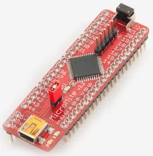
Because the 44-pin chip is surface mount you need to solder it on a printed circuit board (PCB) for it to be useful.
A good solution is the PCB illustrated on the right which is available from Silicon Chip magazine for less than $5:
https://www.siliconchip.com.au/Shop/8/2770
Anouther good solution is to buy a mounting printed circuit board such as Part Code: 44PINTQFP from Futurlec which costs US$1.20. This brings the pins out to a standard 0.1" pitch headers that are much easier to work with.
Suppliers of the bare (un mounted) chip include:
- The Silicon Chip online store also sell the bare 44-pin chip programmed with the Micromite MkII firmware.
- Microchip Direct sell the blank 44-pin microcontroller for US$4.09 as do the normal distributors (at a slightly higher price). You will need a programmer such as the PICkit 3 (or a clone) to load the MMBasic firmware into the chip (see this page for details).

GPS Clock
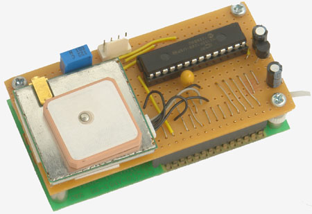
To illustrate how easy it is to use the Micromite, part 1 of the Silicon Chip article (May 2014) described a GPS controlled digital clock based on the Micromite which uses just a few components. It is always accurate to a fraction of a second and never needs setting.
A more detailed description of the clock can be found here.
