
Garden Watering System Controller
![]()
![]()
![]() To automatically water your garden you need a watering controller (also called a reticulation or irrigation controller).
To automatically water your garden you need a watering controller (also called a reticulation or irrigation controller).
This design will do it all; it will control up to eight sprinkler systems, will change its schedule depending on the time of year, will check the weather forecast and change the schedule accordingly and it will send you an email if a pipe has burst or a sprinkler is blocked.
Commercial controllers generally use a tiny LCD display and buttons to program the watering schedule. This design is different - instead you program it via web pages on your phone, tablet or computer. As a consequence it is very easy to program and use.
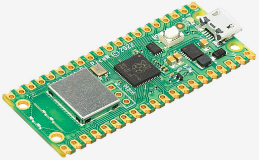
Nearly all the work is done by a Raspberry Pi Pico W microcontroller programmed in BASIC. The program is in plain text and can be easily edited to suit your preferences.
This project was described in the August 2023 issue of Silicon Chip magazine. This web page provides a shorter description so, if you are building this project or would like the full story, you are encouraged to read the magazine article.
Back issues of the magazine can be purchased from Silicon Chip or electronic access can be purchased for about the cost of the printed issue - so it is good value.
WebMite
 The Raspberry Pi Pico W microcontroller used in this project is running the WebMite
firmware described on this web page.
This firmware allows you to easily generate web pages on the Pico W microcontroller and access resources on the internet.
The Raspberry Pi Pico W microcontroller used in this project is running the WebMite
firmware described on this web page.
This firmware allows you to easily generate web pages on the Pico W microcontroller and access resources on the internet.
In part this project was developed to demonstrate the power of the WebMite firmware and provide a resource for programmers who can use some of the code and techniques in their own projects based on the WebMite.
The Watering Controller program will run on a bare Raspberry Pi Pico W microcontroller and that means that you do not need to build anything to test this project. Just load the firmware on a spare Pico W.
Typical Watering System Layout
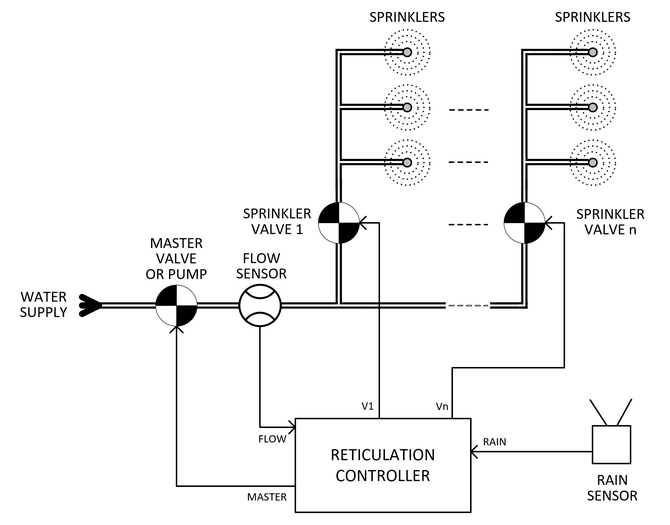 This diagram shows a typical garden watering system layout.
The water supply is fed through a master valve which acts as backup to cut the water supply if one of the sprinkler valves is stuck open. This can also be a pump which will supply the pressure needed.
In either case the controller will turn this device on just before opening the first sprinkler valve and close it just after the last sprinkler valve has been closed.
The flow sensor is optional but the controller can use this to detect excessive water flow from a burst pipe or reduced flow from a blocked valve or sprinkler head.
It does this by building an average of the flow rate through each sprinkler valve. Then, in the case of an abnormal flow rate, it can terminate running that valve and send an email to alert you to the fault.
The rain sensor is also optional. The controller can check the local weather forecast for you and not run the sprinklers if rain is forecast, however a rain sensor provides a backup specific to your garden. The controller will check the rain sensor before starting a sprinkler run and, if it shows that it is currently raining, the controller will not run that schedule for that day.
The master and sprinkler valves are the standard domestic solenoid water valves which are driven by 24V AC and draw about 250mA when open (with a 400mA surge when activated). Normally there are a number of sprinkler heads attached to each valve and the controller can control up to eight sprinkler valves. Using separate valves allows for different amounts of water to be applied to different parts of the garden. When running a schedule the controller will open each sprinkler valve in sequence for the programmed time. This means that at any one time only two valves will be open (the master and the current sprinkler valve).
Main Controller Page
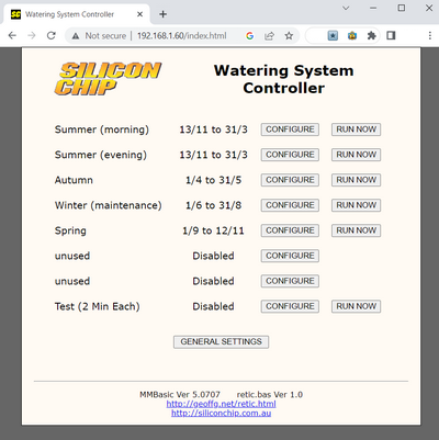 The image on the right shows what the home web page of the controller looks like.
You can have up to eight schedules with each running in different (or the same) parts of the year. For example, one schedule could be for the summer months, another for autumn (when less watering is required), another for winter and so on.
This means that you do not need to reconfigure the controller for each season. You can setup the whole year's sequence of watering schedules and it will continue to run these year after year forever.
The CONFIGURE button for each schedule lets you customise the settings for each schedule as described below.
If a schedule has at least some watering times configured the RUN NOW button will appear which allows you to manually start the watering schedule at any time with the click of the button.
Finally, at the botton of the page the GENERAL SETTINGS button will allow you to configure the location, sensors and the email facility (described further below).
Configuration Pages
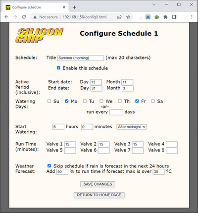
When you click on the CONFIGURE button you will see a page like this. It specifies all the settings for a particular schedule.
The Title field will allow you to set the schedule's name (as shown on the home page) to something meaningful. The schedule can also be completely enabled or disabled with the following check box.
The next four fields set the date in the year for the schedule to start and end. These are inclusive and can overlap with other schedules if needed.
Following this the watering days can be selected as days in the week, or as a certain period (eg, water on every third day).
The start watering time can be selected as so many hours/minutes after midnight (ie, a fixed time) or a certain number of hours/minutes before sunrise, after sunrise, before sunset or after sunset by using the drop down list.
Following this the run time in minutes for each valve can be specified. Any valve with a zero or blank time will be skipped.
Finally, you can specify if the schedule should be skipped if rain is forecast and also increase the watering time for very hot days.
General Settings
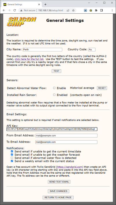
In the general settings page you can specify your location, the connected sensors and the email settings.
The location is important as it is used to determin the timezone, daylight saving adjustment, sun rise/set and the weather. You can run the controller without setting the location but it will be fixed to the time zone of UTC+10 hours with no daylight saving compensation, sun rise/set, etc.
To set the location enter your city's name and the two letter country code, then click on TEST. Following this the web page will update with either success or fail. If you cannot find your location try for a nearby city in the same timezone and general location. For large cities you can also enter a suburb's name and that might work.
The next section can be used to configure the flow and rain sensors. If an abnormal flow is detected the controller will flash the status LED and place a message on the home page but these may be missed. So you should configure the email system (below) to alert you of such an event.
When an abnormal flow is detected the unusual readings will be gradually added into the average maintained by the controller and, after time, they will not be treated as an error. For this reason you should immediately act on any warnings that you may receive.
After fixing the fault you can click on the RESET button to reset the historical average and let the controller build a new average.
The final section is used to configure the email facility.
This uses the free SMTP relay service offered by Twilio SendGrid which allows for 100 emails per day (plenty for this application).
You need to create a free login at SendGrid (https://sendgrid.com) and generate an API key which is a 79 character alpha numeric string starting with "SG" that is used to authenticate your access to their servers. This key then should be entered in the API Key field.
You also need to enter the From Address which must MUST be the same as the address that you specified when you obtained the SendGrid API key. If they are not the same SendGrid will reject the email (this is an anti spam precaution). The To Address can be set to whatever you like including being the same as the From Address.
To test your settings you can click on the SEND TEST EMAIL button and you should get a confirmation message stating that the test email was successfully sent. You can then check the inbox on your To Address to confirm that the email was indeed received.
With this setup you can configure which email notifications that you wish to receive by clicking on the appropiate checkboxes.
Remember that you can load the firmware onto a bare Pico W and test how it works without having to build anything, |
Updated Firmware
A new version of the firmware (V1.3) is available. This upgrade should be used for new builds and applied as soon as possible to an existing build. This is because it corrects two serious faults:
- The firmware was not driving the correct I/O pins as listed in the schematic.
- An error in calculation could cause the controller to water on the wrong day.
Also, a new SMTP relay service for sending emails (SMTP2GO) has been added. Some users have reported difficulties in opening a free account with SendGrid. Now SMTP2GO can be used and their account creation process is much easier to navigate. Finally a number of minor changes has improved the usability and appearance of the web pages generated by the firmware.
Version1.3 is available for download from the bottom of this page.
Schematic
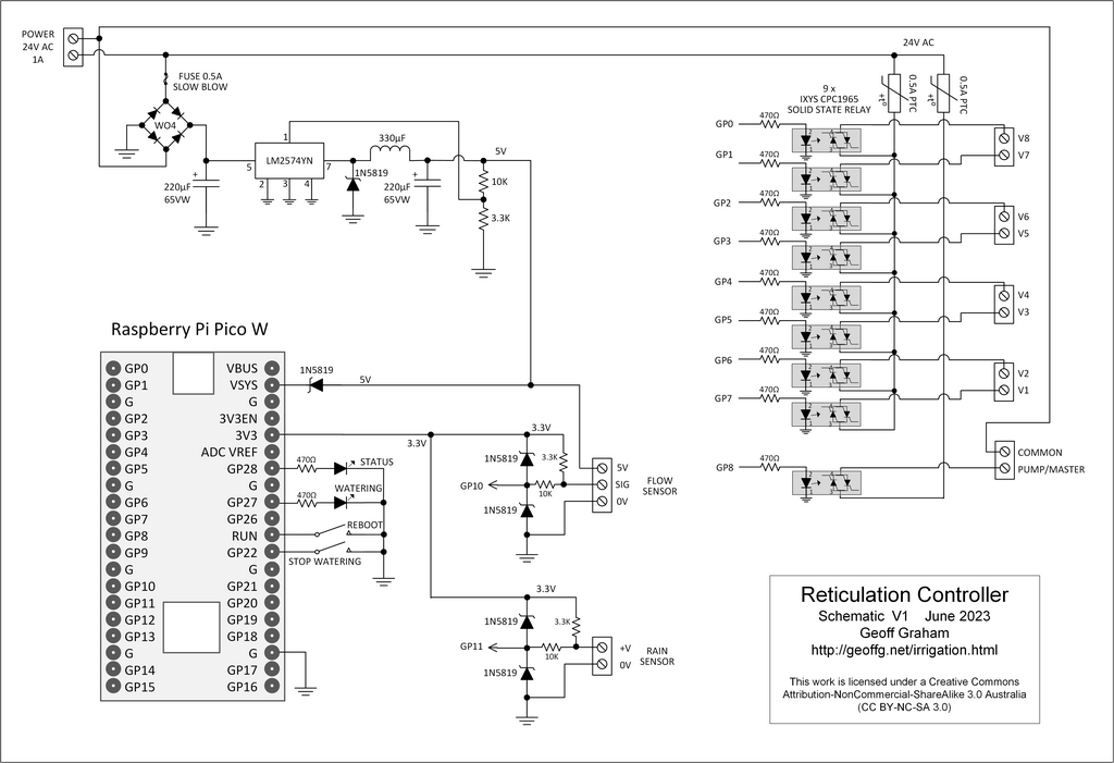 The circuit (also contained in the Construction Pack) is quite simple. Each valve is driven by a Solid State Relay which is optically isolated and switches on the zero voltage crossing of the AC waveform. The Pico W directly drives these to control the nine valves (8 sprinkler valves + master valve). There are two sensor inputs (flow and rain sensors) and both are pulled up to 3.3V by a 3.3K resistor and have a protection circuit of two shotkley diodes which clamp the input to between zero and 3.3V.
The power supply (5V DC) is a simple buck regulator chosen for its reasonable efficiency. This reduces the amount of heat generated within the controller's housing as that could affect the life of the two electrolytic capacitors used in the power supply.
Construction
Detailed build data is contained in the Construction Pack which can be downloaded at the bottom of this page. This contains the schematic, parts list, the firmware and construction notes. Because of this this section only contains a brief description of how the Watering Controller is put tpgether.
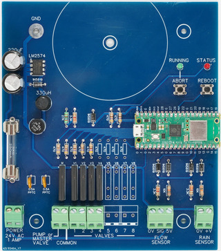
The PCB board is illustrated below and is designed to fit in a waterproof enclosure suitable for mounting outdoors. While it is designed to control eight valves you do not need to install that many relays if you have less valves to drive. Similarly the sensor inputs are optional and if you will not be using them you can leave their protection components out of the build.
The controller runs from a source of 24V AC with a capacity of more than 0.75A (typically 1A), This can be provided by a plug pack (examples are listed in the Construction Pack) or by a small toroid transformer mounted directly on the PCB. Note that if the latter option is used an electrician will be required to correctly terminate the primary and wire it into a house power circuit.
Photos
 |
 |
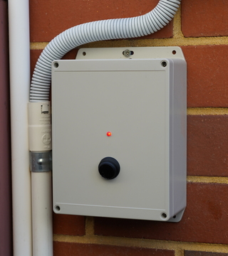
| The controller in its waterproof box on an exterior wall. I elected to mount the status LED and a waterproof power switch on the lid. Note that there are no other controls; all setup is done via web pages. |
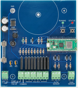
The fully populated PCB. The input/output screw wiring terminals are along the bottom. Above the terminals for the valves are the Solid State Relays and above the two sensor inputs are their protective circuits. The power supply is along the left hand side of the PCB. |
 |
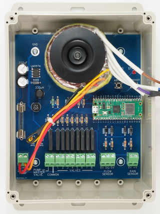 |
| The PCB populated to support just four sprinkler valves. | The PCB mounted in its waterproof enclosure and with the optional power transformer mounted. Note that along the bottom there is plenty of space for arranging the wiring to the valves and sensors. |
| V1.3 Firmware including loading instructions | DOWNLOAD |
| Construction Pack including the schematic, parts list, PCB fabrication files, etc. | DOWNLOAD |