
GPS Controlled Clock
![]()
![]()
 This project is intended to show just how easy it is to use the Micromite for a complex task.
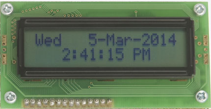
It is a digital clock which gets its time from a GPS module. It has split second accuracy, it will automatically compensate for daylight saving and the clock never needs setting.
The GPS Controlled Clock is based on a single IC (the Micromite) and uses just seven additional components.
The Micromite is an easy to use microcontroller that uses the BASIC programming language. For a full description of the Micromite see this page.
It was introduced in the May 2014 issue of Silicon Chip magazine and the article used the GPS Controlled Clock as a demonstration of what you can do with the Micromite. This Web page provides a short description of the clock however the full magazine article included a more detailed description of the circuit and the program running on the Micromite. If you wish to you can purchase that issue as a back copy or you can buy digital access to that particular issue for about the same cost as the printed issue.
Circuit
The circuit is quite simple and uses just eight components:
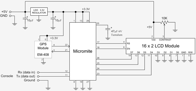
The Micromite is responsible for getting the data from the GPS Module and driving the LCD display - so most of the work is done by the BASIC program running on the Micromite.
The main power comes from a USB 5V adapter/charger (these are cheap and can be found on eBay for as little as $10). This 5V is used to directly power the LCD module and is dropped to 3.3V by the voltage regulator which supplies power to the Micromite and the GPS module.
The only other item of note is the console connection for the Micromite. Connecting a serial terminal to this allows you to load the BASIC program onto the Micromite and edit it if necessary.
Parts List
1 x 28-pin Micromite
1 x 2 line 16 characters per line LCD Display module (eg, Z7001 (Altronics) or QP5512 (Jaycar))
1 x GPS Module (eg, EM408)
1 x 3.3V fixed Voltage Regulator (eg, MCP1700-330, LP2950CZ-3.3, etc)
1 x 47µF 16VW tantalum capacitor
2 x 10uF, 6.3V capacitors
1 x 10K trimpot
You can use many different types of LCD displays so long as it is supported by the LCD command in MMBasic (see the Micromite User Manual for details). The voltage regulator can be any 3.3V regulator with a drop out voltage of 1.2V or less.
You can also use a different GPS Module if you wish as all modules will generate the RMC message (which contains the date and time). Some modules require a 5V power supply and/or a different baud rate which can be accommodated by editing the BASIC program (see downloads below). At the time of writing dx.com have a
cheap EM408 module with RS232 output for US$17 (check the Micromite User Manual which describes how to connect to a RS232 device).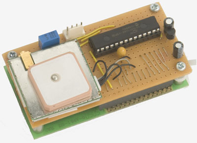
Construction
The simplest method of building the clock is to mount a section of perforated strip board on the back of the LCD module and assemble the components on that board. This arrangement is shown in the photograph on the right.
The power supply is a USB 5V adapter/charger and the best method of connecting to one of these is to cut off one connector on a USB cable and solder the wires directly to the strip board - the other end can then plug into the USB adapter/charger.
Depending on your needs you might also want to mount the completed clock in a suitable enclosure.
The Program
All of the work required to bring the clock to life is performed by the BASIC program running on the Micromite (this can be downloaded below).
The program first waits for a message from the GPS module, it then checks that it is an RMC message and that the GPS module has a lock on sufficient satellites to get an accurate time. The program then extracts the components of the date/time as numbers (eg, the year, month, day, hour, etc).
The GPS time is UTC (ie, Greenwich) time and must be converted to the local time by adding the time zone offset. Another adjustment that may be necessary is to compensate for daylight saving. To make these adjustments the program converts the time to minutes since midnight on the 1st January 2014. It is then easy to add/subtract the time zone offset and daylight saving adjustment. Once these adjustments have been made the time is then converted back to ASCII strings for display on the LCD.
At the start of the program there are two variables that must be set.
TimeZone is the offset of your local time from UTC. It can be positive or negative and it can be a fraction (for example, -6.5 is six hours thirty minutes before UTC).
UsedDST is a flag indicating if daylight saving compensation should be used. If it is zero DST will be disabled and if non-zero DST compensation will be applied.
Note that the daylight saving rules are for Australia. For other countries you will have to adjust the variables dms, dhs, dme and dhe (their functions are explained in the program). You may also have to change the way that the function GetDST() works.
| GPS Controlled Clock program for the Micromite | DOWNLOAD |