Micromite Explore 64
![]()
![]()
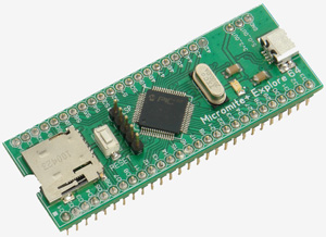
 The Explore 64 is a small board designed by Graeme Rixon that includes a 64-pin Micromite Plus, a micro SD card socket, a USB socket and power supply and is designed to plug into a standard solderless breadboard.
The Micromite Plus is a 32-bit microcontroller running a BASIC interpreter called MMBasic. This is compatible with Microsoft BASIC and includes floating point, integer and string variables, arrays, long variable names, a built in program editor and many other features.
With the Micromite Plus and MMBasic you can use communications protocols such as I2C or SPI to get data from a variety of sensors. You can measure voltages, detect digital inputs and drive output pins to turn on lights, relays, etc. Special features include the ability to use temperature sensors, distance sensors and more.
The standout feature in the Micromite Plus is support for large (up to 8 inch) LCD display panels and its advanced graphics which include on screen controls such as radio buttons, check boxes and alphanumeric keypads. This makes the Explore 64 perfect for many control situations from a simple pump controller to a sophisticated industrial controller.
This page provides a description of the hardware features of the Explore 64. For details of the Micromite Plus and the MMBasic programming language refer to the Micromite Plus web page.
Sourcing the Explore 64
Graeme Rixon of Rictech (who designed the Explore 64 PC board) offers blank boards, kit of parts and fully assembled and tested boards. These can be purchased from his website: http://www.rictech.nz/micromite-products.
Over time Graeme has updated his version of the Explore 64 and it now includes a Microbridge which acts as a USB to Serial bridge and a PIC32 programmer. This allows you to update MMBasic running on the chip without any extra hardware. Because the Microbridge provides the Serial to USB function it means that you will not lose the USB connection to your desktop computer when the Micromite is reset - something that was annoying in the original design. More details are on his website.
Silicon Chip magazine also sell blank boards, a kit of parts and a pre programmed 64-pin Micromite Plus chip from their on line shop: http://www.siliconchip.com.au/Shop/
The Explore 64 featured in Silicon Chip magazine in August 2016. This web page provides a much shorter description so, if you would like the full story, you are encouraged to read the magazine article. Back issues of the magazine can be purchased from Silicon Chip or electronic access can be purchased for about the cost of the printed issue.
Features
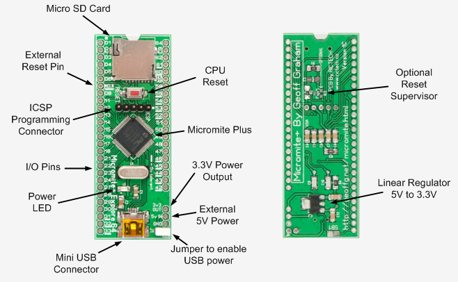
There is not a lot to say about the Explore 64. It is really just a PC board carrier for the Micromite Plus chip and a few extra components and connectors.

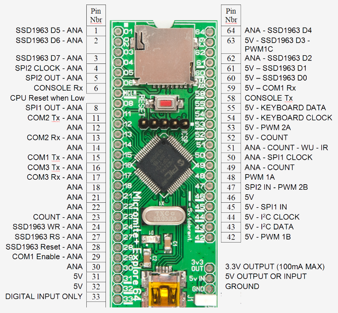
I/O Pin Allocations

Notes:
- Pin Nbr refer to the number used in MMBasic to identify an I/O pin.
- All pins (except 33) are capable of digital input/output and can be used as an interrupt pin.
- ANA means that the pin can be used as an analogue input.
- 5V means that the pin is 5V tolerant.
- COUNT means that the pin can be used for counting or frequency/period measurement.
- SSD1963 refers to pins that are used to interface to LCD panels using the SSD1963 controller.
- If the serial console is disabled the CONSOLE pins can be used for COM4
Console Connections
Note that you do not need to use an external USB-Serial converter as shown here if you are using the 1E version or later of Graeme Rixion's version of the Explore 64. This is because his later versions now includes a Microbridge which acts as a USB to Serial bridge and a PIC32 programmer. The 1E version of the Explore 64 can be purchased from his website: http://www.rictech.nz/micromite-products.
However, if you are using an earlier version of the Explore 64 this is how you can connect the popular CP2102 USB-Serial converter to the Micromite's console.

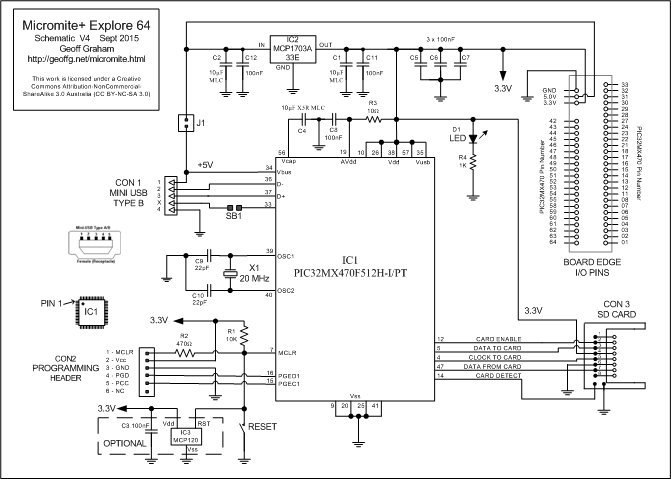
Schematic
Essentially the Explore 64 consists of just the Micromite Plus and a few peripheral components.
Points to note are:
- The 3.3V supply for the Micromite plus is obtained from 5V via a low dropout linear regulator. This supply is also made available on the edge pins and can be used to supply external circuitry up to 100mA.
- IC3 is a reset supervisor which holds the PIC32 in reset whenever the supply voltage is below 2.7V. It is optional and for normal use is not required. However, in an electrically noisy environment its use is recommended.
- The jumper J1 can be used to power the Explore 64 from the USB connector. If the board is powered externally (via the 5V pin on the board's edge) this jumper should be removed.
- The signal lines to the SD card socket are also connected to pins on the board's edge. This allows them to be used as general I/O if the SD card facility is not used.
- The 10µF capacitor C4 must be a ceramic preferably with a XR5 dielectric. It is used to stabilise the 1.8V regulator inside the PIC32 chip and is critical to the reliable operation of the chip.
Click on this image for a high resolution diagram
Parts List
1 PCB 72mm x 27mm
1 Tactile switch, two pin, surface mount
1 20MHz crystal, low profile
1 Micro SD card socket (Altronics P5717 or similar)
1 Mini USB socket (Altronics P1308 or similar)
2 50 pin 0.1" male header strip
Semiconductors
1 Microchip PIC32MX470F512H-120/PT (120MHz) or PIC32MX470F512H-I/PT (100MHz)
1 Microchip MCP1703AT-3302E/DB voltage regulator (SOT-223)
1 Microchip MCP120T-270I/TT supervisor (optional)
1 LED Green, SMD 1206 package
Capacitors
2 22pF Ceramic, SMD 1206 package
7 100nF Ceramic, SMD 1206 package
3 10μF Ceramic, SMD 1206 package, preferable XR5 dielectric
Resistors
1 10Ω, SMD 1206 package
1 470Ω, SMD 1206 package
1 1K, SMD 1206 package
1 10K, SMD 1206 package

