
Water Level Meter
![]()
![]()
 This is a gadget that will estimate the amount of water left in the water tank of a caravan or camping unit.
Many caravans, mobile homes, camper vans, etc have a water system which uses a 12 volt pump to supply water from an inbuilt tank. The pump is commonly controlled by a pressure sensitive switch. When a tap is opened, the pressure in the water line drops, the switch closes, and the pump runs supplying water to the user. When the user closes the tap, the pressure in the water pipe rapidly increases, causing the pressure sensitive switch to open and stop the pump.
Many such systems do not have a method of indicating the amount of water remaining in the tank. This forces the user to estimate the amount of water remaining and guess when the water tank should be refilled. A mistake can mean that you run out of water when you are camping in the bush and a long way from a convenient tap.
This device will display the estimated amount of water in the water tank and also provides a simple indicator of the level of charge in the caravan/camper's batteries.
Description
The water meter function operates by timing how long the water pump has been running. The water pump will deliver a constant amount of water for every second that it runs, and the meter can estimate the remaining water level by comparing the running time with the amount of time that it would take to drain a full tank.
The longer the pump runs, the more water that must have been consumed, and correspondingly, the more empty the tank must be. It is a simple calculation to subtract how long the pump has run from how long it takes to empty the tank. The result is displayed on an illuminated bar graph which shows the estimated amount of water remaining.
The meter is calibrated by storing the time it takes to empty the tank using a typical usage pattern. The firmware can accomodate a tank that empties in as little as a few minutes to a tank that empties over hundreds of hours, so it will work with almost any tank and pump combination. The microcontroller also times consumption with a resolution of one fiftieth of a second, so it will record the shortest of "blips" by the water pump.
The battery function will estimate the remaining charge in the caravan/camper's batteries. This is done by precisely measuring the battery voltage and calculating the amount of remaining charge based on typical 12 volt lead acid battery discharge characteristics. Full scale is 12.9 volts and zero display is at 11.4 volts and the display runs linearly between these two points.
Water Level
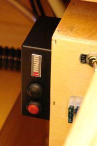
The amount of water in the tank is displayed as a bar graph of ten LEDs. These are always illuminated so that a simple glance is all that is required to ascertain how much water is left. Even though the display is always illuminated it will not drain a normal 12V battery used in a caravan or camper as the LEDs consumes little power compared to the capacity of the battery.
When the water tank has been filled, the meter must be reset so that it can accurately calculate the following consumption of water. To reset the water meter you should hold down the red (reset) button for 4 seconds or more. As you so this the whole bar graph will flash to indicate that a reset is about to happen. The reset can be done at any time (for example if a partly empty tank is filled). Note that the tank must be filled to the brim when the reset button is held down as the meter has no other way of knowing the starting level of the water.
Battery Capacity
To display the battery capacity, press the black (battery) button. When the button is released it will revert to showing the water level. The battery reading will be higher if the battery is under charge, or lower if being drained, so a more reliable reading will be obtained if none of these are occurring and the battery has been allowed to settle for 20 minutes or more.
Water Tank Capacity Calibration
The water meter function is calibrated by filling the tank and resetting the meter to full (as described above). Then the water should be used normally until the tank runs dry. Then, press the red (reset) button and, while holding it down, press the black (battery) button. Hold down both buttons for over 4 seconds. The meter will store the amount of time that it took to drain the tank as its new calibration constant. This calibration can be repeated as many times as necessary.
Disconnecting the caravan or camper’s battery will not affect the meter as it will store the calibration value and the current water level in internal memory. This memory will hold its values for more than 50 years without power.
Circuit Description
A full scale version of the schematic is available form the download section at the end of this page.
 The pump is monitored by the 0.1 ohm resistor in series with its negative battery connection. A typical pump will draw 2 to 3 amps when running and this will generate 200 to 300 mV across the resistor. This voltage is compared by the PIC microcontroller (using its built in analog comparator) to a 90 mV reference voltage on pin 14. The result of this comparison indicates if the pump is running and is used internally by the microcontroller software to time the running time. This design will accommodate any pump that draws between 1 and 5 amps.
The 10K resistor and 1uF capacitor on pin 1 of the microcontroller are used to reduce the electrical noise which is created by the pump.
The black (battery) switch and the red (reset) switch pull their respective inputs on the microcontroller low when pressed. The inputs to the microcontroller are normally held high by pull up resistors within the chip.
The remainder of the input/output pins on the microcontroller are used to drive the LED bar graph. The bar graph consists of 10 independent red LEDs. In this circuit we wire them into two banks of 5 LEDs each. The firmware in the microcontroller multiplexes between the individual LEDs in each bank at high speed so that the illumination appears constant. To understand this, take the case where all LEDs are illuminated. First the microcontroller will turn on LED 1 and LED 6, then a short time later LED 2 and LED 7, and so on to LEDs 5 and 10 where the cycle restarts. If a LED is not required to be on, the microcontroller will not turn it on when its time slice comes up. This multiplexing means that we can control all 10 LEDs with just 5 lines and 2 current limiting resistors.
The final section of the circuit is the power supply which uses a 5V regulator designed for automobile use. It can withstand high voltage transients and noise that is common in the automotive environment.
Because the device will be used in a high vibration environment, all components should be soldered in. Soldering the microcontroller to the board will prevent its removal for programming (if required). To overcome this issue, the design includes an In Circuit Serial Programming (ICSP) connector. This is optional, but handy if you wish to experiment with the firmware.
Firmware
The firmware running on the microcontroller was written using the CCS C compiler and the MPLAB programming environment. The HEX file for programming into the microcontroller and the source code (if you wish to modify the program) is available below.
Construction and Installation
The circuit was assembled on a small piece of veroboard and mounted into a plastic case that attached to the side of the fuse box in the camper. As each caravan/camper will be different you will have to work out your own method for packaging and installing the meter.
The prototype was built for an Active Camper. This is a camping unit that mounts on the back of a 4WD utility as shown below. If you have an Active Camper you can download detailed instructions to suit the camper from the downloads below.
| Schematic v1.0 | DOWNLOAD |
| Firmware - HEX programming file and source code v1.0 | DOWNLOAD |
| Active Camper Version - Installation Notes | DOWNLOAD |