1st Generation Colour Maximite 2
![]()
![]()
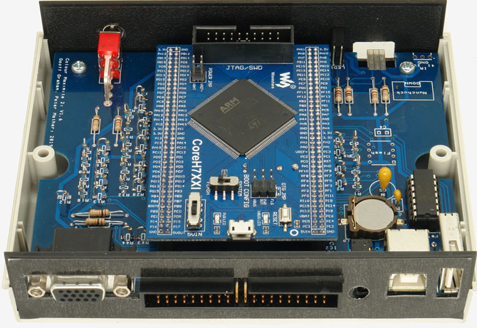
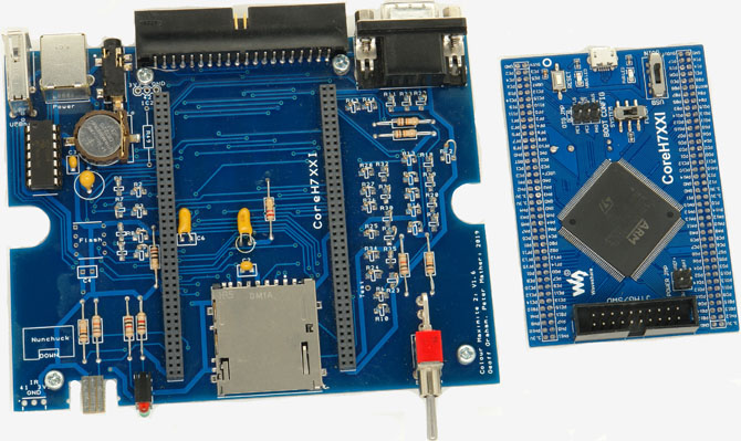
This version of the Colour Maximite 2 was the first version released and was designed to be easy for home constructors to build. The main board is a simple double sided design with mostly thru hole parts and can be built in an hour or two.
For other pages related to the Colour Maximite 2 see:
Hardware Tour
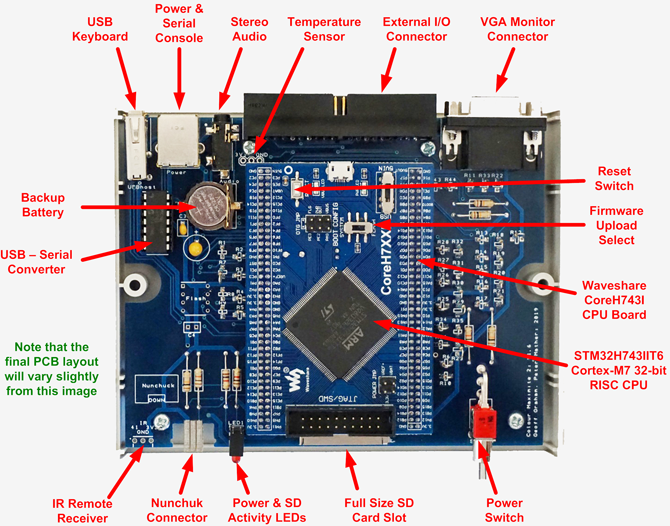
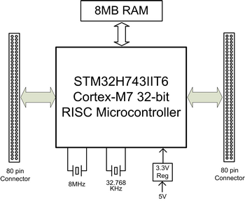
The Waveshare CoreH743I CPU Board is the brains of the first generation Colour Maximite 2. This plugs into the motherboard which holds the interface components and connectors - most of of which are connected directly to the Cortex-M7 32-bit RISC processor on the Waveshare board. Most functionality is provided by this processor which includes holding the BASIC program in flash, generating the VGA output, etc.
The Waveshare board also includes 8MB of SDRAM and various support components.
The plug in board concept eliminates the need to solder the ARM CPU with its 176 pins and 0.2mm gap between pins. It also allows the whole CPU system to be easily replaced if it is suspected that the CPU has been damaged.
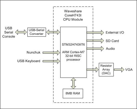
The overall layout is illustrated in the block diagram on the right.
- The Waveshare board holds a 32-bit ARM Cortex-M7, an 8MB SDRAM chip and other support components.
- The mother board holds the connectors, a USB to serial converter and the resistor ladders used to generate the analog VGA output.
The advantage of this design choice is that the constructor does not have to solder the 32-bit ARM Cortex-M7 chip which has 176 closely spaced pins. Also, if it is suspected that the processor has been damaged it can be easily swapped out for another module. The module is reasonably cheap so using this will not break the bank.
Waveshare CoreH743I CPU Board
 The Waveshare CoreH743I Board can be purchased from Waveshare, eBay and AliExpress.
As shown in the block diagram it essentially consists of the 32-bit ARM Cortex-M7, an 8MB SDRAM chip, a voltage regulator and a couple of crystals. Most pins on the CPU chip are routed directly to the two 80-pin connectors on each side of the board.
Further details of this board including its circuit diagram can be found on the Waveshare website at https://www.waveshare.com/coreh743i.htm
The ARM Cortex-7 microcontroller has the part number STM32H743IIT6. It runs at up to 480MHz and has 2MB of flash memory and 1MB of RAM.
It uses a 32-bit RISC (Reduced Instruction Set Computer) architecture which is optimised to 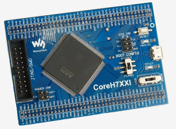 run a small set of instruction very fast. This microcontroller does almost everything needed to make the computer work including running the BASIC interpreter, holding the BASIC program in memory, communicating with the keyboard and controlling the external I/O pins.
The chip has an on-chip video processor which is quite sophisticated and generates a rock solid VGA output at 800x600 pixels and up to 65,536 colours. The CPU also includes a hardware double precision floating point processor implemented in the silicon hardware of the chip so it is very fast.
There are two versions of the STM32H743IIT6. The older version is Rev Y and it runs at 400MHz while the later version is Rev V which runs at 480MHz. The version letter is engraved on the IC but you can also tell which one that you have by using the command PRINT MM.INFO(CPUSPEED) which will tell you the speed of the chip. Because both versions share the same part numbers vendors may end up supplying either version (it is our of their control)..Regardless, both are very fast and work the same.
Motherboard
The motherboard contains mostly passive components and a USB to Serial converter chip. The passive components include the various connectors (VGA, I/O, etc), the resistor ladders for the VGA analog signals and a backup battery (for the clock in the STM32 chip). Most devices such as the Nunchuk, SD card, etc connect directly to the STM32 processor via the two 80-pin connectors.
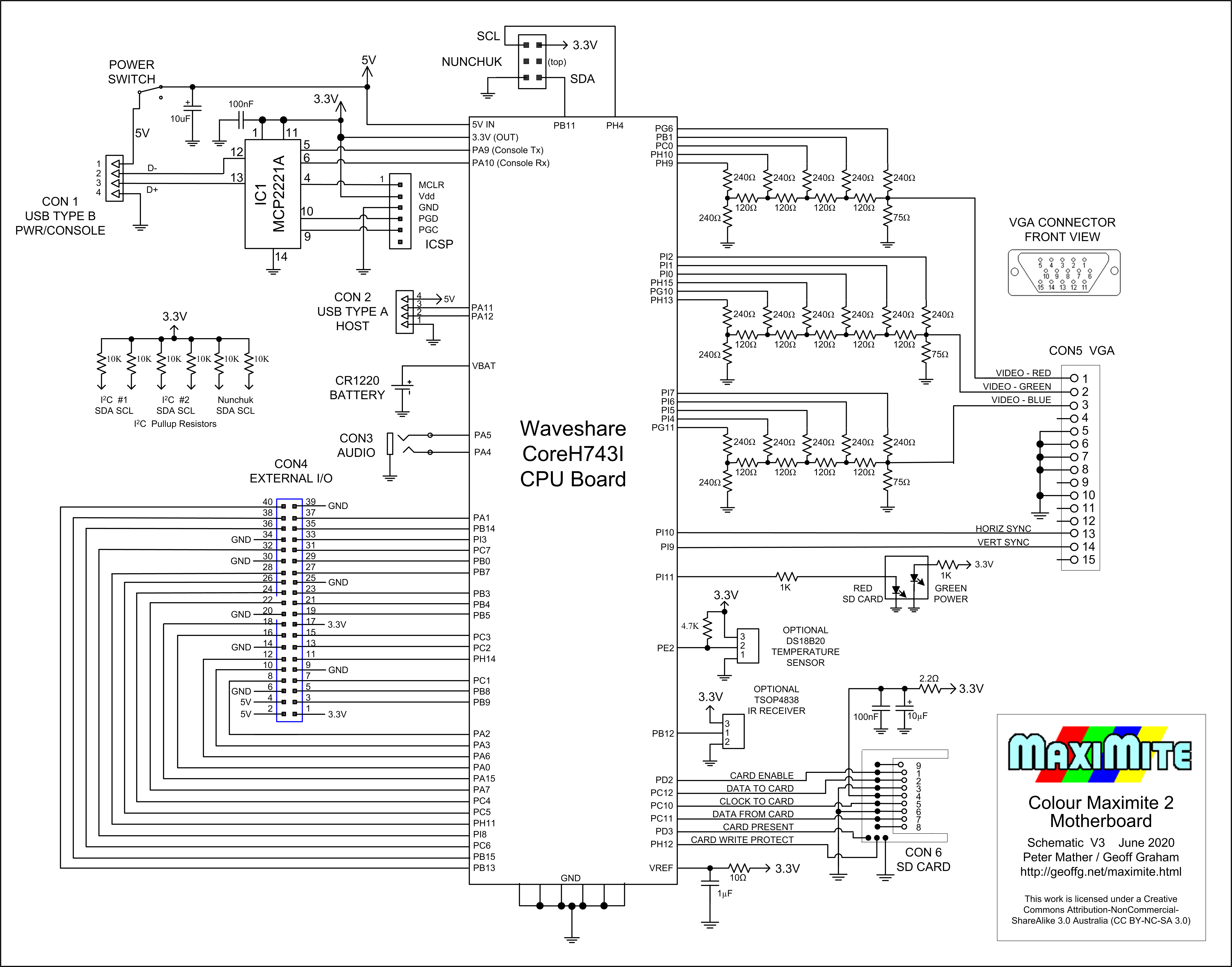
(click on the image to see the full size drawing)
IC1 is a USB to Serial converter and can be either the Microchip MCP2221A or a Microbridge (see this page). This chip allows a personal computer to connect to the Colour Maximite 2 and access its console using the serial over USB protocol.
The backup battery is a CR1220 coin cell which keeps the internal STM32 real time clock running while the power is off and also keeps a bank of 4KB RAM alive (this is used for configuration information and saved variables).
The VGA signal is generated by the STM32 processor via 16 digital output lines which are used for the red analog signal (5 bits), green (6 bits) and blue (5 bits). These drive three resistor arrays which act as digital to analog converters to generate the analog red, blue and green signals. The arrays are R–2R ladders which require a total of 35 resistors. Because of this large number and to save space these resistors are mounted vertically. They are all through hole types however, if you are confident in soldering SMD components, you can use 1206 sized surface mount resistors as the pads are sized to take these as well.
(This is a prototype of the PCB. The final design differs slightly)
Construction
The Colour Maximite 2 Construction Pack contains everything that you need to build the computer including the PCB fabrication files, parts list and instructions. This can be downloaded from the bottom of the main Colour Maximite 2 WEB page.
The construction pack contains notes on the parts required and assembly hints so you should find it easy to assemble. However, if you need a full description of the construction process you should refer to the July 2020 and August 2020 issues of Silicon Chip magazine. Back issues of these articles can be purchased from Silicon Chip or electronic access can be purchased for about the cost of the printed issue