
Building the Monochrome Maximite
![]()
![]()
This page describes the circuit of the original monochrome Maximite and how it works. It then goes on to describe two different methods of building it into a working computer.
The mini Maximite has its own web page.
For details of the original (monochrome) Maximite click on these:
- Description and Specifications
- The mini-Maximite, a miniature version of the Maximite for embedded systems
- The DuinoMite, a Maximite clone
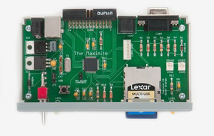
The amazing thing about the Maximite is that it consists of just a single chip (the Microchip PIC32) that drives everything and does all the work. The only other significant items in the circuit are the power supply (two simple regulators) and a number of resistors to ensure that the outputs are at the right level.
This is illustrated in the circuit diagram below (click on the image for a larger view):
.jpg)
You can use one of two variants of the PIC32 chip in this circuit, either the PIC32MX795F512H-80I/PT or the PIC32MX695F512H-80I/PT (don't you love that part numbers that semiconductor manufacturers use). The only difference is that the latter chip does not include the CAN interface which we are not using anyway. Both chips run at 80MHz, have 512KB of flash program memory and 128KB of RAM. It is this huge RAM capacity that makes the Maximite possible, most high powered chips have only 16K or 32K of RAM and that is insufficient to implement a BASIC interpreter with the capability of that used in the Maximite.
To describe the circuit I will move around the chip in a clockwise direction starting with the video output in the top right of the diagram.
The components shown in the schematic allow the video configuration to be switched between VGA and composite by JP2. You actually have the choice of three configurations as shown in the table below.
| VGA Only |
Composite Only |
Selectable VGA or Composite |
|
|---|---|---|---|
| R4 | Leave Empty | 680Ω Resistor | 680Ω Resistor |
| D1 | 1N4148 Diode | 120Ω Resistor | 1N4148 Diode |
| JP2 | Leave Empty | Permanent Link | Jumper or Switch |
The selectable VGA/composite mode does not produce as quite a good picture as the dedicated modes but it is still very good. When VGA is selected the black level is not truly black and for composite the white level is not as bright as it could be - however the monitor can be adjusted to compensate for these effects or you can use the components for a dedicated mode and get the perfect picture.
The jumper JP2 is checked at power up so you need to cycle the power to change modes (with JP2 shorted composite is selected).
The video is generated by a standard SPI peripheral within the PIC32 chip. This is continuously fed with data by the DMA circuitry which reads a section of memory and feeds the data to the SPI peripheral so that there is a constant stream of ones and zeroes being clocked out on pin 6 of the chip. These bits represent the video signal for a horizontal line with each bit being a pixel. The beauty of this scheme is that it happens independently of the CPU which only needs to write the required pixel data to the allocated section of memory and service an interrupt for the horizontal sync pulse.
The technique is described by Lucio Di Jasio in his book "Programming 32 bit microcontrollers in C” which is well worth reading if you are interested in learning more about programming for the PIC32.
An important part of the circuit is R5 which feeds the horizontal sync pulses back to the SPI peripheral so that the start of the data stream is synchronised to the pulse. This removes any jitter that may be caused if the CPU was used to start the data stream and results in a very steady image on the screen.
Sound
 Using MMBasic the SOUND command will generate a square wave between 20Hz and 1MHz on pin 49 for the sound output. The resistors in the circuit diagram drop the voltage to a level suitable for an amplifier.
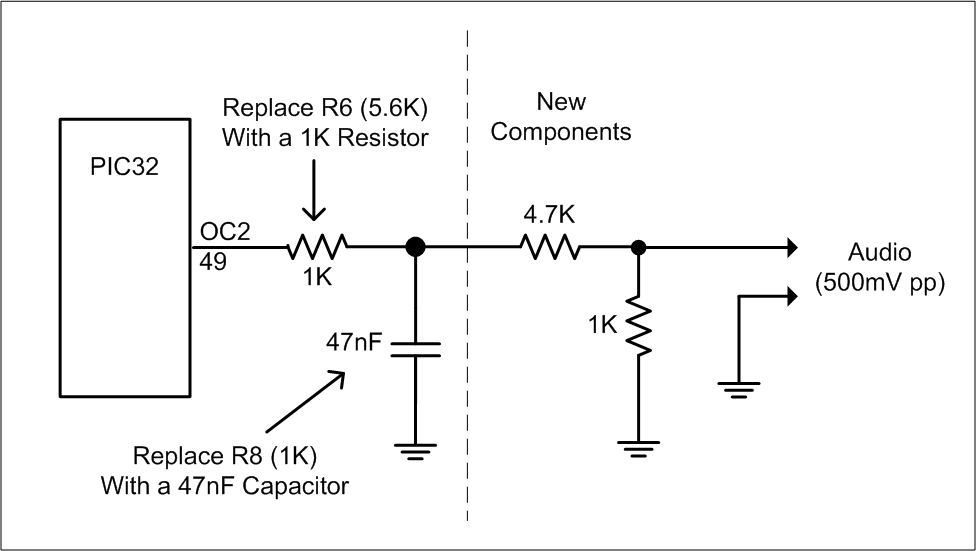
Later versions of MMBasic added the TONE and PLAYMOD commands to generate a sine wave tone and play music. These require a low pass filter on the pin 49 as illustrated in the circuit on the right.
Pin 49 can also generate a Pulse Width Modulated (PWM) output for generating an analog output using the PWM command. If you are using this command you will need to change the values used in this circuit to something more suited to your application.
Pin 58 drives the power indicator LED. This is only illuminated after the firmware has successfully completed the startup sequence so it acts as confirmation that everything is OK. When in bootload mode the firmware will flash this LED to show that it is not running the BASIC interpreter and is ready to load a new version of the firmware.
The IBM keyboard is connected to pins 54 and 55. The firmware enables the on chip pullup resistors for these pins and the keyboard will pull the pins low when it wishes to send data representing a keystroke.
The SD/MMC/SDHC card is also directly connected to the PIC32 and uses the SPI mode which is supported by all three card types and is royalty free (unlike the native communication mode). The card is clocked at 20MHz which results in reasonably fast transfers. The 33K resistors R9 and R10 are used to pull up the card enable and data lines to prevent them from floating during power up which could cause random writes to the card (that would be disastrous). Most of the other lines are pulled high by pullup resistors in the PIC32 and enabled by the firmware.
External I/O
CON8 is the connector carrying the 20 external input/output signals. The IDC connector odd pin numbers can be configured for analogue input or digital input or output while the even pin numbers can only operate as digital I/O but have the capacity of working with 5V circuits.
Note that other than the standard protection inside the PIC32 these pins are unprotected from damaging voltages. Where static electricity is concerned the PIC32 is well protected by reverse biased diodes integrated on the chip but you still need to guard against a large static discharge that could blow these diodes. Generally a high value resistor to ground on floating inputs will protect against this.
Another danger is SCR latch up which can be caused by a large current (>20mA) being forced through the protective diodes. 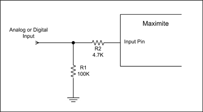 This could happen if the Maximite is connected to another circuit that is powered up before the Maximite and in this case the best protection is to include a series resistor to limit the current on any susceptible inputs.
This reference will tell you about both issues and the circuit on the right illustrates the suggested protection measures.
Note that in a most practical situations the input circuitry (be it an accelerometer, voltage divider, etc) will provide enough protection so you do not have to go overboard on the subject.
Programming Header
Returning to the schematic. CON3 is an ICSP (in circuit serial programmer) header and is used to program the chip if you are using a virgin PIC32. You will not need this if you have built the Maximite from a kit as the kit supplier will have pre programmed the chip for you. If you do plan to program the chip yourself probably the best programmer to choose is the Microchip PICKit 3 which is cheap and fully supports the PIC32.
The boot load button is connected to pin 47 which has an internal pullup resistor enabled and is used to initiate the bootload sequence if the button is pressed on power up. When in the bootload mode the Maximite will appear as a different USB device (a HID device) and wait for new firmware to be downloaded via the USB interface. A Windows program will be supplied with any updates and it is this software that knows how to communicate with the Maximite and reprogram the firmware while it is in the boot load mode.
The crystal X1 connected to pins 39 and 40 provides the main clock for the chip. This is multiplied internally to provide the 80MHz clock for the processor core in the PIC32 chip.
If your Maximite does not start up the problem could be caused by C5. A sure indicator is that the power LED does not light and the Maximite draws very little current (normal consumption is about 125mA). C5 must be a low ESR Tantalum capacitor and the PIC32 is very sensitive to its characteristics. If you suspect C5 try replacing it with a higher value and/or a higher working voltage (both of these will improve the ESR). Also try another brand. Some readers have had success by wiring another Tantalum capacitor (22 or 47µF) from pin 56 (Vcap) of the PIC32 to the 3.3V supply. It is not certain why this would work but it is worth a try. |
The USB interface (CON2) is simple enough, it directly connects to the PIC32 as all the required components (pullup resistors, transceiver, etc) are integrated in the chip. The firmware monitors the voltage on pin 34 and uses that to detect when the USB interface is connected to a host computer.
Pin 56 on the top of the PIC32 in the schematic is connected to the internal 1.8V regulator that supplies power to the high speed processing core of the chip. C5 and C12 provide noise filtering for that regulator.
Pin 19 is the power supply for the analog portions of the chip and R2 in conjunction with C6 provides some isolation from the main 3.3V supply (which is quite noisy).
The power supply is very simple providing +5V which is only used by the keyboard and +3.3V which is used by the PIC32 and the SD card. There are four 100nF capacitors on the output of the 3.3V supply and these are distributed on the PC board close to the power pins of the PIC32 where they help reduce transients on the power line.
Loading the Firmware
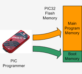 When you buy a PIC32 chip from Microchip is is supplied completely blank. So, the first thing that you must do is program the chip with the firmware included in the construction pack (available at the bottom of this page). This operation is illustrated on the right.
This firmware must be loaded by a PIC programmer (such as the PICKit 3) and includes both the main program (including MMBasic) and a boot loader. The boot loader sits in a special region of memory and is used to upgrade the firmware at a later date.
You only have to bother with this stage if you bought the PIC32 chip direct from Microchip or similar. If you bought the Maximite from a kit supplier they will have already programmed the chip for you, so you can skip that step.
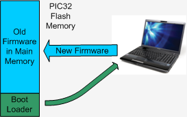 Once the boot loader is in place you can update the firmware via the USB interface and a Windows computer.
Full instructions will be included with the update but in essence the boot loader is run at power up and its job is to download the new firmware and reprogram the main program memory (as illustrated on the left).
Once the boot loader is in place you can update the firmware via the USB interface and a Windows computer.
Full instructions will be included with the update but in essence the boot loader is run at power up and its job is to download the new firmware and reprogram the main program memory (as illustrated on the left).
Because the boot loader is located in a protected area of memory it is completely unaffected by failures when programming the main memory. For example, if you loose power or accidentally unplug the USB cable while programming you can just go back to the beginning and restart the boot load process – the boot loader will never be corrupted or lost.
The first thing you should do after building the Maximite is go to the main page (link) and download the latest version of the firmware. You can update the firmware in the Maximite as many times as you like, for example to test a an earlier version or experiment with a special version.
Construction
The simplest way to build the Maximite is to buy the kit from Altronics as it includes everything including the original magazine article which describes the construction in detail.
You can also download the Maximite Construction Pack at the bottom of this page. It contains all you need to build the Maximite including the circuit, parts list, PCB layouts, firmware, etc. You can make your own board or send the Gerbers to a PCB fabricator who will make them for you. The blank PIC32 chip can be purchased from microchip.com or futurlec.com. All the other parts are generic and can be sourced from many suppliers.
A better (and cheaper solution) is to buy The PCB board and the PIC32 chip from Silicon Chip magazine. The chip supplied by Silicon Chip is pre programmed with MMBasic so you do not need a programmer. Subsequent updates are loaded via a Windows computer and USB.
The parts you need to order are:
Construction takes an hour or two and don't be put off by soldering surface mounted devices, it is easy, see my web page Surface Mount is Easy.
If you have a problem after constructing the Maximite the first thing you should do is read the Frequently Asked Questions page as that covers at least 99% of the hardware related problems that constructors have experienced. Other support options and resources are listed on the main Maximite web page.
An Alternative Maximite
As you can see from the schematic at the start of this page, the Maximite consists of just the PIC32 chip and a collection of connectors. All you really need is the chip itself, X1 (the crystal), R1 and R2, and the capacitors C3 to C12. Everything else is optional. Based on this premise the remainder of this web page will describe an alternative method of building the Maximite that will cost under $20.
One caveat though, to use this technique you do need to be reasonably experienced in electronics.
This simple version only includes the USB interface. As you can enter, edit and run BASIC programs using just the USB interface (and a desktop computer) this is still a working Maximite. Later you can add the SD card, video, etc if you want to.
The circuit for this version is shown below and is the same as the full version except for the missing interfaces:
.jpg)
The technique and construction of the header board described below is the same as described in my PIC32 article in the March 2011 issue of Silicon Chip. If you have that issue you will find a much more lengthy description of how to wire up the header board for the PIC32 chip.
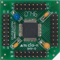
To get started you need a header board that can take a 64 pin LQFP or TQFP package with 0.5mm pitch leads. A good choice is the 64PINLQFP from Futurlec for 90 cents (also available on eBay). You can buy the PIC32 chip pre programmed from Silicon Chip or, if you have access to a programmer capable of programming the PIC32, you can buy a blank chip from from Microchip and Futurlec.
You can use many methods to solder the chip to the header board but I found that a soldering iron and a good magnifier was all that I needed. For more details see my web page Surface Mount is Easy.
 I then soldered dual row header pins around the edge of the breakout board which I used to connect to a solderless breadboard via female to male patch leads. On the breadboard I placed the crystal (X1), its associated load capacitors (C3 and C4), the pull up resistor for MCLR (R1), the USB connector (CON2) and the ICSP connector (CON3).
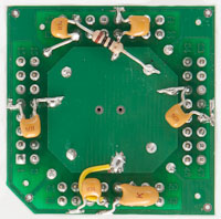
R2 and the remaining capacitors need to be mounted as near as possible to the power supply pins on the PIC32 to keep the power glitch free. I mounted these on the underside of the breakout board as shown in the photo on the right (note that this photo is different from that used in the Silicon Chip article on the PIC32).
The board has an outer copper ring that I used for Vss (ground or 0V) and an inner copper pad that I used for Vdd (3.3V). The chip needs a power supply of between 2.3V to 3.6V for Vdd and this can be provided by two Alkaline batteries or a standard power supply.
If the chip is blank you will need to program it (the firmware is available in the download section below) using a programmer like the PICKit 3. Then, connect the board to your desktop computer via USB and install the Windows Serial Port Driver (also available in the download section). The final step is to run a terminal emulator (I like Terra Term but any will do), connect to the Maximite virtual serial port and press ENTER. 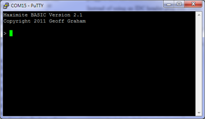 You should be rewarded with the MMBasic prompt as shown below.
You can add items such as the video and keyboard connectors by following the full Maximite schematic at the top of this page.
Rather than using the breadboard to hold the extra components (as I did), you could omit the header pins on the header board and solder the crystal and extra components direct to the solder pads on the board. The board would be a bit crowded but would result in a completely self contained computer on the header board. This could then be used as a handy embedded computer system that could be the core of any project that needed a powerful and versatile processor. And at a cost of under $20.
For details of all Maximites go to the main Maximite page. The following links will take you to other pages related to the original Maximite.:
- Description and Specifications
- The mini-Maximite, a miniature version of the Maximite for embedded systems
- The DuinoMite, a Maximite clone
Other useful pages:
- MMBasic introduction
- The MMBasic home page at http://mmbasic.com
- Firmware downloads
- Frequently Asked Questions
- The Maximite Story (how it came about)
| Original (monochrome) Maximite Construction Pack | DOWNLOAD |