GPS Synchronised Clock
![]()
![]()
NOTE: This page is a very much out of date now - it is retained here for archival purpopes only
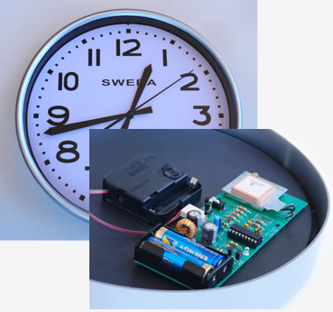
This project replaces the electronics in a standard quartz wall clock with a circuit that uses GPS satellites to get the precise time.
Features include:- Keeps time with an accuracy of a few seconds.
- Automatic adjustment for daylight saving time (stepping clock mechanisms only).
- Easy to use... Just set the hands and insert the batteries. The clock will either wait for the right time or step at double speed until it reaches the correct time.
- Can be configured to run in any timezone and with different daylight saving rules.
- Batteries last for 12 months.
- Drives a standard wall clock (either stepping or with a sweep second hand).
- Uses a relatively cheap (US$70) GPS module. For notes on using the EM-408 GPS module see this page.
INTERMITTENT DAYLIGHT SAVING ERROR Ver 2.0 of the firmware for the stepping clock contains a subtle bug which will cause the clock to start or end daylight saving time (DST) exactly one week late if DST happens to start or end on the first day of the month. If you are using the default settings of the firmware this would have happened for the first time on the 1st April 1012. The next event will occur at the start of DST on 1st October 2017 (five years away). Version 2.1 of the firmware fixes this problem and can be downloaded from the bottom of the page. My apologies for the inconvenience. This does illustrate the difficulty of testing something that only happens very intermittently. Geoff Graham 3rd April 2012 |
There are two versions of this clock controller, one for clocks that step every second (the most common type) and a second version for clocks that have continuous sweep hands. The second type of movement can be found in the newer upmarket clocks from Seiko and Citizen. You can also buy replacement continuous sweep movements on the Internet for $10 to $15.
The main difference between the two is that clocks with a stepping type movement produce an annoying “tock” sound every second while the continuous sweep clocks are silent.
Controller for stepping clocks:
- The design was published in March 2009 by Silicon Chip (SC) magazine. The March 2009 Silicon Chip magazine can be purchased online using the above link for about the same cost as the paper version of the magazine and it contains everything that you need to know about building the clock.
- Everyday Practical Electronics (EPE) magazine also published the design in their March 2011 issue.
- The stepping clock version will automatically adjust for daylight saving time and can be configured to run in any timezone and with different daylight saving rules.
- You just need to set the hands to exactly 12 noon and insert the batteries. The clock will step at double speed until it reaches the correct time and then keep perfect time after that.
Controller for continuous sweep hands clocks:
- The design was published in the November 2009 edition of Silicon Chip magazine. It is a simple modification of the original (March 2009) design requiring the addition of just two diodes and two wire links. You can also purchase this issue of the magazine online for about the same cost as the paper version of the magazine.
- Due to the mechanics of a continuous sweep movement this controller cannot adjust for daylight saving time (sorry).
- To start the clock you should set the hands to exactly the next hour or half hour and insert the batteries. The clock will wait until it reaches the correct time and then start running, keeping perfect time from there.
Both types of controller will keep the time to an accuracy of a few seconds. In practice the accuracy is even better than this (often within a second) and will be maintained over the life of the battery. The only caveat is that I have found that the swept hand movements are much more tempermental to deal with and they are more sensitive to the battery voltage so they tend to stop earlier. So, if you have a choice it would be better to go with a stepping clock movement.
Note that this web page only carries details not published by Silicon Chip and Everyday Practical Electronics in the original articles.
Complete Kit of Parts
You can buy the complete kit of parts for the March design (unmodified) from Altronics (http://www.altronics.com.au). The short kit (without the GPS module) is available as Altronics part number K1129, the EM-408 GPS module is part number K1131. If you want to drive a continuous sweep movement the modifications described in the November 2009 SC article can be easily made to this kit as the PC board has been modified to suit and the extra components are included. The kit includes the original magazine article so it is a good way to proceed if you have not read the article.
Notes and Errata for the March 2009 (SC) and 2011 (EPE) Article
This is the full list of notes and corrections to the March 2009 SC and March 2011 EPE article. Unfortunatly Everyday Practical Electronics did not include all these corrections in their reprint:
- In Fig 1 and Fig 2 the markings for the GPS voltage selection were reversed. To set the circuit to 3.3 volts to suit the EM 408 module the jumper must be placed on the pair of pins nearest the PIC chip, i.e. opposite to that shown in the photographs.
- Figure 4 (Experimenting with the GPS module) should be modified as follows:
- Replace the connection from pin 12 of the MAX232 to pin 3 of the GPS module with a 4.7K resistor.
- And connect a 10K resistor from pin 3 of the GPS module to ground.
Without this modification the EM-408 GPS module may be damaged by excessive voltage on pin 3 (serial data input). - The schematic (Fig 1) has the tip and ring of the phono socket CON1 reversed. In addition, the cable wiring diagram (Fig 3) has the sleeve and ring of the matching phono plug reversed. The correct diagram is shown below. The Errata published in the April edition of Silicon Chip is incorrect and the cable is suitable for programming PICAXEs.
- The original firmware posted on the Silicon Chip website did not allow the New Zealand timezone (+12 hours) to be configured. The updated firmware (listed below) corrects this issue.
- In firmware versions earlier than 1.5b the clock will wait for some time (hours) before it starts double stepping if you insert the batteries when the local time is between 9:00 and 12 o'clock. When it does start double stepping it will catch up with the correct time and keep perfect time after that. This bug is corrected in ver 1.5b and later.
- When you first insert the batteries the microcontroller will wait forever for data from the GPS. The two minute timeout only applies to synchronisations after the clock is running.
Notes and Errata for the November 2009 SC Article
The November 2009 Silicon Chip article contained corrections for most of the previous errata but unfortunately a few extra crept in:
- The PC board layout and circuit diagram still showed the incorrect markings for the GPS voltage selection. To set the circuit to 3.3 volts to suit the EM 408 module the jumper must be placed on the pair of pins nearest the PIC chip, i.e. opposite to that shown in the PCB layout. Make sure that you check the voltage to the GPS module before you plug the module in, it should be 3.3V. This is the only safe way of getting it correct.
- The wiring of the setup cable seems to be the Bermuda Triangle of blunders. In the November 2009 article the cable wiring diagram for the setup cable (Fig 7) has the wrong numbering of the pins on the DB5 connector. Use the diagram below, it is correct.
- You should change the 10uF capacitor to 47uF. This will give you 5 seconds to insert BOTH batteries before the microcontroller starts running. See the item on “Startup Problems” below for a full description of why this is needed.
Updated Firmware
The latest version of the firmware (along with the source code) is available from the download section at the bottom of this page. There are two versions, one for stepping clocks and one for continuous sweep clocks.
The stepping clock version will work with the original design as described in the March 2009 (SC) or March 2011 (EPE) articles or the modified design described in November 2009 by Silicon Chip. The firmware does this by detecting if the controller has been modified and changing the way it works to suit. Because this version contains a number of bug fixes it is recommended that you upgrade regardless of what version you are currently running.
Setup Cable for the PC
During production of the March and November 2009 articles a sequence of errors resulted in the diagram for the setup cable being wrong (see erratas above). The following diagram summarises the correct wiring. You can also find this diagram in the download section below.
PIC16LF88 vs PIC16F88
The article mentions that the F version of the chip should work in place of the LF version. Since then, many chips have been tested and all PIC16F88 chips worked fine at below 2V and most happily carried on working at 1.5V. So, unless you have a LF chip handy, don't bother looking for it. In reality, all chips are probably made on the same production line and the only difference is the testing and labeling.
Startup Problems
If you have modified your board as described in the November 2009 article you may experience intermittent problems with the startup of the microcontroller when you insert the batteries. With the original design the capacitor on pin 4 (the reset pin of the micro) held the micro in reset for about a second after you inserted the batteries. This delay gave you sufficient time to fully seat the batteries before the micro started running.
With the modifications detailed in the November issue a slightly different sequence occurs. What happens is that when you insert the first battery, current will flow through the clock's coil and via either D3 or D4 to the main supply rail. The result is that the main supply rail will be at approx 1.25V (battery voltage minus one diode voltage drop). The capacitor on pin 4 of the microcontroller will charge through the 100K resistor and within a few seconds reach 1.25V. When the voltage exceeds 80% of the supply voltage (1.25V at this time) the micro will be taken out of reset but, as it cannot operate at 1.25V, it will not run its program. Then, when you insert the second battery, the supply voltage will shoot up to 3V and the micro will start running immediately. The problem with this is that you are still inserting the second battery and the intermittent contact with the battery connector may cause the voltage to jump up and down with the result that the micro hangs.
This means that you must insert BOTH batteries before the one second reset expires and this is very hard to do. The solution is simple—replace the 10uF capacitor with a 47uF capacitor. This will give you about 5 seconds to insert both batteries. The only issue is that now you must remember to hold down the setup button for over 5 seconds if you want to enter the setup menu.
Modifying a Clock Mechanism
Experience has shown that the easiest way to get at the stepper motor in a clock mechanism is to remove the front glass of the clock and then pull off the hands. This makes it possible to remove the mechanism as a whole unit. Normally the hands are just a friction fit onto the shafts and can be removed by pulling them away from the dial.
With the hands removed you will probably find that the clock mechanism is held onto the dial by either :
- A nut around the shaft poking through the dial which carries the clock's hands.
- Plastic clips on the back of the dial which hold the clock mechanism in place.
With the mechanism free and in your hands you can lever up the side clips and pop off the cover and get at the stepper motor. Be warned, some of the plastic gears will fall out so make a quick sketch to help you later reassemble the mechanism.
Generally the clock’s built in controlling IC is hidden under a blob of black epoxy and you should be able to see two tracks leading from it to two solder pads which terminate the wires from the stepper motor coil. You need to isolate the IC so cut one of the tracks and solder your two wires to the pads terminating the stepper motor coil.
Variations in Stepper Motor Resistance
This section only applies to the unmodified controller board. The modified controller board is not affected by the resistance of the stepper motor coil.
The sensitivity and resistance of clock stepper motor coils seem to vary considerably with the cheaper models having a lower resistance than the more upmarket ones. The 270 ohm resistor in series with the stepper motor was chosen as a compromise but you may have to vary it to suit your clock and ensure that it still steps reliably at low battery voltages.
The best way to do this is to:
- Set a variable power supply to 3V, connect it to your clock controller, and wait for the clock to start double stepping.
- While the clock is stepping, reduce the voltage to 1.95V and check that the second hand will reliably step right around the dial with the clock held in its normal (vertical) orientation.
- Reduce the value of the 270 ohm resistor if the second hand hesitates at some point. Some clocks need as low as 120 ohms.
Reliability at Low Battery Voltages
You can test the ability of your clock to run at low battery voltages by using a variable power supply in place of the batteries. If you have modified your controller as described in the November 2009 article you will also need to connect two 47 ohm resistors in series across the output of the power supply to simulate the mid point between the two batteries.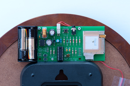
This setup allows you to test the ability of the DC-DC converter to startup at this low voltage by disconnecting and reconnecting the power while the power supply is set to 1.95V. You should get all four flashes on the startup LED, as per normal. If the GPS module does not start (i.e. you do not get 3 flashes) this probably means that the DC-DC converter cannot work at low voltages. This is normally due to an incorrect inductor or non low ESR capacitors being used, but it could also be due to the MAX756 having a higher startup voltage as discussed in the March 2009 Silicon Chip article.
Other tests include running the clock for an hour as described in the November 2009 article to test that the stepper motor can operate effectively at low battery voltages.
Note that at this low voltage the RS232 interface to your PC will probably not work. It was designed to work with a battery voltage of 2.8V or higher.
Indicating an Error
The early versions of the firmware stopped the clock at 12 o'clock when there was any sort of error. This made it difficult to distinguish between a flat battery and something else.
The current versions stop the clock at different positions to indicate the type of error:
- Clock stopped at 10 minutes before the hour or half hour means GPS module has stopped communicating (no 3.3V, module faulty or not plugged in).
- Clock stopped at 5 minutes before the hour or half hour means that the GPS could not find enough satellites (low signal level).
- Clock stopped at exactly the hour or half hour means low battery.
These error modes are covered in more detail below.
When the CPU halts it will turn off all internal components and go into a sleep mode with negligible current draw (<1uA). This ensures that the clock will not further drain the batteries which could cause them to leak.
This low current draw also means that the charge on the capacitors will remain for some time after you remove the batteries, and therefore the microcontroller may not recognise the reset condition when you replace the batteries. The symptom is that when you replace the battery you do not get a single (or any) flashes from the LED.
This will mostly occur if you have an error condition and you try to reset the microcontroller by momentarily popping out a battery and replacing it. The solution is to take your time replacing the batteries or short the battery contacts together for a second to discharge the capacitors.
GPS Failure
Situations where the GPS Module does not respond should be very rare, but it can happen due to a couple of causes:
- The MAX756 cannot deliver a stable 3.3V. Try testing as described in "Reliability at Low Battery Voltages" above.
- The GPS Module or its connecting cable might have failed.
If this happens the firmware will retry every 4 hours and after the 10th consecutively unsuccessful retry will stop the clock at 10 minutes before the hour or half hour.
Loss of GPS Signal
When the clock first starts up it uses the GPS module to get the current time. If it cannot lock onto sufficient satellites (i.e. not enough signal) it will keep trying forever and you will not see four flashes from the LED.
Normally this should be sufficient but it is possible that the clock could be moved to another location after it has started and that the new location does not have sufficient signal level. In that case the GPS will not get a reliable satellite lock when it next tries for a synchronisation. If this happens the firmware will retry every 4 hours and after the 10th consecutively unsuccessful retry the firmware will wait for the clock to reach 5 minutes before the hour or half hour and then stop.
All this means that, if you do not get a GPS lock, the clock will stop 40 to 52 hours after the first failure. Because the clock will remain reasonably accurate over this period this ensures that the clock will halt before it shows an inaccurate time.
Flat Battery
How does the firmware handle a flat battery?
Every time the firmware starts up the GPS Module it also measures the battery voltage. This measurement is made at the point of peak current draw for the EM-408 so that the reading reflects the true capacity of the battery. The firmware waits for four consecutive low readings before it declares the battery flat. It then waits until the hands (stepping at the normal rate) reach the exact hour or half hour before halting.
This means that, assuming the GPS synchronisation interval is set to 44 hours, the clock will wait for between 176 and 188 hours (approx 7 days) from first discovering a flat battery before it stops. Given the light current draw this delay is not an issue and prevents a glitch from shutting down the clock prematurely.
Bigger Battery
AA batteries were chosen because they were small enough to fit on the PC board and still gave a reasonable battery life. But, with a big clock and plenty of room, there is no reason why you could not use larger batteries in a couple of  "outboard" battery holders. Two C cells should last about 3 years and two D cells over 5 years. Imagine, a clock that you do not have to touch for 5 years, and it will always be accurate, even after all that time.
If you have mains power handy another option would be to use a couple of rechargeable batteries and constantly trickle charge them (via a suitable resistor) from a plugpack. If the power failed, the rechargeables should be able to power the clock for months. You will have to make sure that the voltage on the battery line does not go too high if the batteries are removed by accident while the trickle charge is running. A 4.7V zenier diode across the battery contacts could achieve that. With this change the clock would run for a lifetime and always be spot on accurate.
Low Signal Levels
The EM-408 GPS module is quite sensitive and in most situations can lock onto sufficient satellites to get the correct time. Unlike an in-car GPS which needs to get a signal all the time the GPS Synchronised Clock can retry for a long time if it cannot get a lock and still keep good time.
If you have a problem with low signal levels (ie, your clock stops at 5 minutes before the hour or half hour) there are a few things that you can try:
- On the very first synchronisation (when you insert the batteries) the microcontroller will keep trying forever to get a signal and, if the module is factory fresh or has not been used for some weeks, it will take 15 minutes for the module to get all the data it needs from the satellites - so all you might need to do is give it enough time.
- Reorientate the GPS module. The best mounting position for the module is horizontally with the antenna on top of the module pointed to the sky. This is the most sensitive orientation.
- Move the GPS module off the board to near a window or some other better location and run wires back to the clock controller. The wires should not be shielded as the capacitance of that type of cable would degrade the signal. Four core telephone cable should be adequate and you should be able to be run it for at least 3 to 4 meters. I have not tested this so some experimentation might be needed.
- Use an external antenna. The gold coloured connector on the side of the module is for this. You need an active GPS antenna with a MMCX connector suitable for a 3 volt module. There are quite a few to choose from, just Google for "GPS antenna MMCX". I have tested this one from from DealExtreme and it worked well. Another example is SparkFun who also sell the GPS module. They have an antenna with a magnetic mount for US$15. This has a SMA connector so you will also need an interface cable MMCX to SMA for US$10.
Design Criteria
Some readers have asked why the design used an analogue clock mechanism when a much more precise result could have come from using a digital display.
This project was intended to make a standard wall clock accurate, so that you did not have to keep climbing up on a chair to adjust the time. It started with the analogue clock mechanism and the GPS module was simply the best way of getting an accurate time signal to control the mechanism.
One reason the GPS Module was chosen was because it could be powered from batteries and the batteries could last a long time. Battery power was important because wall clocks generally do not have mains power handy. Also, the analogue clock mechanism only needed time source with an accuracy of a few seconds and the GPS Module easily met that requirement.
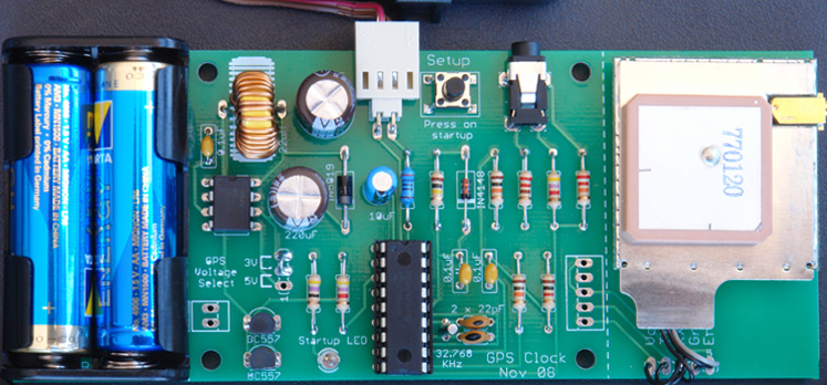
Printed Circuit Board
The photographs above and below show the original printed circuit board designed for the project. Silicon Chip designed a different PCB which is now very hard to get unless you have purchased an Altronics kit (which includes it).
You can download the original PCB design from the download section below. This is in the Gerber format - refer to this short description if that terminology is new to you. You can send this off to a fabrication house who will make the board for you. I use seeedstudio who do a good job at a reasonable cost.
If you use the original board then the errata 1 and 3 (listed above) do not apply. However, you must reverse the tip and ring connections on the phono connector when constructing the setup cable as described above in “Setup Cable for the PC”. Also, Fig 1 (schematic) in the Silicon Chip article is correct and accordingly the setup cable will NOT be PICAXE compatible.
| Firmware - HEX programming file and source code v2.1 for Stepping Movements NEW | DOWNLOAD |
| Firmware - HEX programming file and source code v1.0 for Continuous Sweep Movements | DOWNLOAD |
| Corrected diagrams for the PC interface cable and schematic | DOWNLOAD |
| Alternative Printed Circuit Board design - source and gerber files v1.0 | DOWNLOAD |