
Micromite Explore 100
![]()
![]()
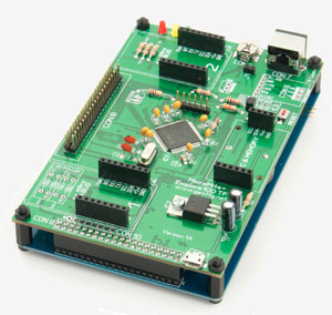
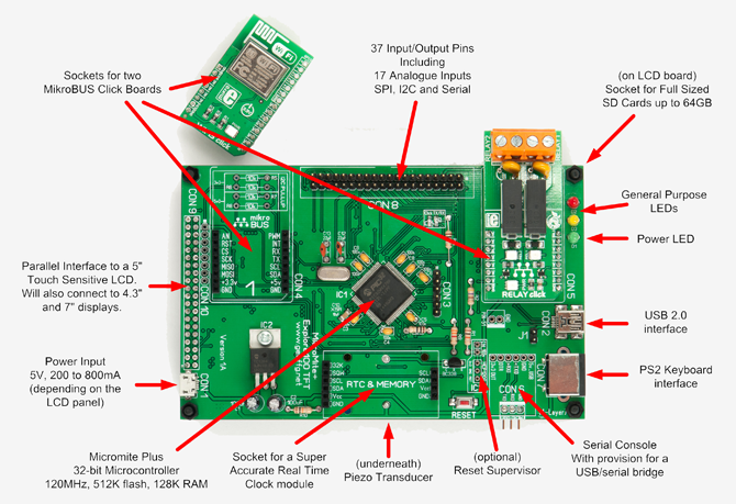
The Explore 100 is designed to fit on the back of a 5 inch touch sensitive LCD display panel. It includes a 100-pin Micromite Plus, USB socket, two sockets for Click Boards and a power supply. The combination of the Explore 100 and the LCD display panel make a rigid assembly that can be mounted in a box or a control panel.
Using MMBasic the LCD panel can display on screen buttons, switches, radio buttons and many more graphic objects. When touched MMBasic will animate these on screen objects and their status can be read by the BASIC program and used to control lights, relays and many other devices.
This means that you can easily build a sophisticated control panel for anything from a burgular alarm to an automated lathe in a short time and still get a professional looking result. All written in the easy to use BASIC programming language.
At the core of the Explore 100 is the Micromite Plus which is a 32-bit microcontroller running a BASIC interpreter called MMBasic. This is compatible with Microsoft BASIC and includes floating point, integer and string variables, arrays, long variable names, a built in program editor and many other features.
With the Micromite Plus and MMBasic you can use communications protocols such as I2C or SPI to get data from a variety of sensors. You can measure voltages, detect digital inputs and drive output pins to turn on lights, relays, etc. Special features include the ability to use temperature sensors, distance sensors and more.
Sourcing the Explore 100
Graeme Rixon of Rictech (who designed the Explore 100 PC board) offers blank boards, kit of parts and fully assembled and tested boards. These can be purchased from his website: http://www.rictech.nz/micromite-products.
Silicon Chip magazine also sell blank boards, a kit of parts and a pre programmed 100-pin Micromite Plus chip from their on line shop: http://www.siliconchip.com.au/Shop/
The Explore 100 featured in Silicon Chip magazine in September 2016. This web page provides a short description so, if you would like the full story, you are encouraged to read the magazine article. Back issues of the magazine can be purchased from Silicon Chip or electronic access can be purchased for about the cost of the printed issue.
Explore 100 Features
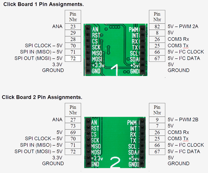
Click Boards
An important feature of the Explore 100 is its ability to use up to two MikroBUS click boards which are a standard developed by the European company MikroElektronika (http://www.mikroe.com/click).
There are almost 200 of these boards including Ethernet interface, Bluetooth, GPS modules, and many more. They can be used to add a specific function to the Explore 100 without having to buils it yourself. One example is the TextToSpeech click board which can be used to make voice announcements from the BASIC programe.
Configuring the Explore 100 in MMBasic
Various features of the Micromite Plus can be set or disabled via OPTION commands which are saved in non volatile memory inside the chip and automatically reapplied on startup. To run these commands you need to use a terminal emulator connected to either the serial console or USB console.
The following commands configure MMBasic for the Explore 100. For further information on these commands and configuring MMBasic refer to the Micromite User Manual and the Micromite Plus Addendum which can be downloaded from: https://geoffg.net/micromite.html#Downloads
- Configure the display: OPTION LCDPANEL SSD1963_5, LANDSCAPE, 48
- Configure the touch interface: OPTION TOUCH 1, 40, 39
- Calibrated the touch interface: GUI CALIBRATE
- Configure the SD Card: OPTION SDCARD 47
- Configure the real time clock (if installed): OPTION RTC 67, 66
To use the Explore 100 as a self contained computer there are some additional configuration commands required.
- Echo all console output to the LCD display panel: OPTION LCDPANEL CONSOLE
- Configure the keyboard: OPTION KEYBOARD US
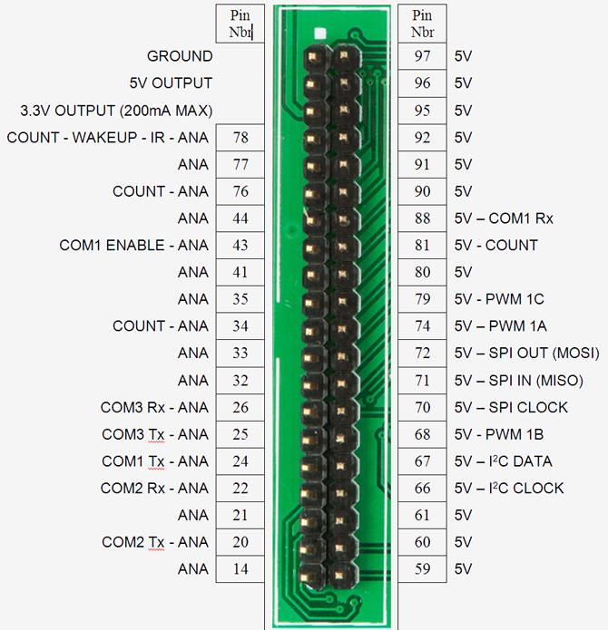
I/O Pin Allocations
Schematic
The Explore 100 is centered around the 100-pin Micromite Plus and most signals travel to and from this chip.
Points to note are:
- Click on the image for a high resolution diagram.
- The final PC board is slightly different from the photographs shown above but matches this schematic. The board from Silicon Chip magazine has a few other changes (refer to the magazine article for the details).
- The 3.3V supply for the Micromite plus is obtained from 5V via a low dropout linear regulator. This supply is also made available on the I/O connector and can be used to supply external circuitry up to 200mA.
- IC3 is a reset supervisor which holds the PIC32 in reset whenever the supply voltage is below 2.7V. It is optional and for normal use is not required. However, in an electrically noisy environment its use is recommended.
- The jumper J1 can be used to power the Explore 100 from the USB connector. If the board is powered externally (via the 5V power connector CON1) this jumper should be removed.
- CON6, the console header is designed to match a standard CP2102 based USB to serial converter (search eBay for "CP2102"). To ensure that the connecting pins and mounting holes align you should purchase a device that matches the image shown on the schematic.
- CON11, the real time clock header is designed to match a standard Maxim DS3231 based RTC (search eBay for "DS3231"). To ensure that the connecting pins and mounting holes align you should purchase a device that matches the image shown on the schematic. This module can be modified to use a standard CR2032 non rechargeable battery - for details see my web page describing the Super Clock.
- The 10µF capacitor C10 must be a ceramic preferably with a XR5 dielectric. It is used to stabilise the 1.8V regulator inside the PIC32 chip and is critical to the reliable operation of the chip.
- For details on configuring and using the RTC, keyboard, USB, buzzer, etc see the Micromite Plus Addendum which can be downloaded from the main Micromite web page.

Click on this image for a high resolution diagram
Parts List
1 PCB 135mm x 85mm, four layer.
1 5 inch LCD display panel with SSD1963 controller, touch and SD card.
-or- a 4.3 or 7 inch display panel (search on line suppliers using the term "SSD1963")
1 5V 1A (minimum) regulated DC power pack with 2.1mm DC connector (centre pin positive).
1 20MHz crystal, low profile
1 23mm buzzer (Altronics S6108) or 14mm buzzer (Altronics S6104 or S6105) (see text)
1 Mini USB socket (Altronics P1308 or similar)
1 6 Pin PCB Mount Mini DIN Socket (Altronics P1106 or similar)
1 Tactile switch, four pin, through hole
1 2.1mm Female DC Power Socket, PCB Mount (Altronics P0620 or similar)
1 40-pin dual row 0.1" female header socket –or- male header plug (see text)
1 40-pin dual row 0.1" boxed male header plug
2 50 pin 0.1" single row female header socket strip (cut and trimmed as required)
1 2 pin 0.1" male header
1 6 pin 0.1" male header
4 M3 untapped spacer 6mm or 7mm
4 M3 machine bolt minimum 16mm with matching nut
1 M3 machine bolt 6mm with matching nut
Semiconductors
1 Microchip PIC32MX470F512L-120/PF (120MHz) or PIC32MX470F512L-I/PF (100MHz)
1 LM3940IT-3.3 regulator, TO-220 package
1 Microchip MCP120-270GI/TO reset supervisor TO-92 package (optional – see text)
1 RF9333PbF MOSFET (optional – see text)
1 BC338 transistor, TO-92 package
1 3mm LED Green
1 3mm LED Yellow
1 3mm LED Red
Capacitors
2 22pF Ceramic, through hole package
11 100nF Ceramic, through hole package
1 10μF Ceramic, SMD 1206 package, preferable XR5 dielectric
2 100μF 16VW Electrolytic
Resistors (¼W, 10% tolerance, through hole)
1 10Ω
4 470Ω
1 1K
1 3.3K
2 10K